Toyota Venza: Removal
REMOVAL
PROCEDURE
1. PRECAUTION
CAUTION:
- Be sure to read Precaution thoroughly before servicing (See page
.gif) ).
). - If the front seat side airbag assembly was deployed, replace the front seat side airbag assembly, front seat frame assembly with adjuster, separate type front seatback cover and separate type front seatback pad with the necessary parts in accordance with the extent of the collision damage.
2. REMOVE FRONT SEAT ASSEMBLY (for Manual Seat)
(See page )
3. REMOVE FRONT SEAT ASSEMBLY (for Power Seat)
(See page )
4. REMOVE FRONT SEATBACK BOARD SUB-ASSEMBLY (for Manual Seat)
5. REMOVE FRONT SEATBACK BOARD SUB-ASSEMBLY (for Power Seat)
6. REMOVE SEPARATE TYPE FRONT SEATBACK COVER WITH PAD (for Manual Seat)
7. REMOVE SEPARATE TYPE FRONT SEATBACK COVER WITH PAD (for Power Seat)
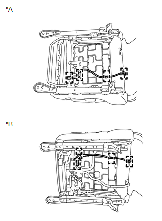
8. REMOVE FRONT SEAT SIDE AIRBAG ASSEMBLY
|
(a) Disengage the 4 clamps and disconnect the wire harness. Text in Illustration
|
|
|
(b) Disengage the 2 clamps and disconnect the wire harness. |
|
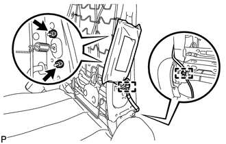
(c) Remove the 2 nuts and front seat side airbag assembly.
CAUTION:
- The nuts must not be reused.
- Make sure that the front seat frame assembly with adjuster is not deformed. If it is, replace it with a new one.
 On-vehicle Inspection
ON-VEHICLE INSPECTION
CAUTION / NOTICE / HINT
CAUTION:
Be sure to follow the correct removal and installation procedures of the front
seat side airbag assembly.
PROCEDURE
1. INSPECT FRONT SEAT ...
 Disposal
DISPOSAL
CAUTION / NOTICE / HINT
CAUTION:
Before performing pre-disposal deployment of any SRS component, review and closely
follow all applicable environmental and hazardous material regulations ...
Other materials about Toyota Venza:
On-vehicle Inspection
ON-VEHICLE INSPECTION
PROCEDURE
1. CHECK BATTERY CONDITION
NOTICE:
If the battery is weak or if the engine is difficult to start, perform the following
procedure.
(a) Check the battery for damage and deformation. If severe damage, deformation
or leaka ...
Transponder Key Amplifier
Components
COMPONENTS
ILLUSTRATION
Removal
REMOVAL
PROCEDURE
1. REMOVE FRONT DOOR SCUFF PLATE
2. REMOVE COWL SIDE TRIM SUB-ASSEMBLY
3. REMOVE LOWER NO. 1 INSTRUMENT PANEL FINISH PANEL
4. REMOVE LOWER STEERING COLUMN COVER
5. REMOVE ...
Internal Control Module Monitoring Processor Performance (P060A)
MONITOR DESCRIPTION
The main CPU and sub CPU of the ECM perform data communication between each other.
The main CPU monitors the communications and WDC pulses from the sub CPU. When the
signal malfunctions below are detected, the DTC is output.
...

0.1342