Toyota Venza: Indicators and warning lights
The indicator and warning lights on the instrument cluster and center panel inform the driver of the status of the vehicle’s various systems.
For the purpose of explanation, the following illustration displays all indicators and warning lights illuminated.
► Instrument cluster
► Center display
- Indicators
The indicators inform the driver of the operating state of the vehicle’s various systems.
 Turn signal indicator
 Headlight high beam indicator
 Headlight indicator
 Tail light indicator
 Automatic High Beam indicator
 Fog light indicator
 Security indicator
 Cruise control indicator
 Cruise control “SET” indicator
 Slip indicator
 VSC OFF indicator
 TRAC OFF indicator
 “AIR BAG ON/OFF” indicator
 Shift position and shift range indicators
- Warning lights
Warning lights inform the driver of malfunctions in the indicated vehicle’s systems.
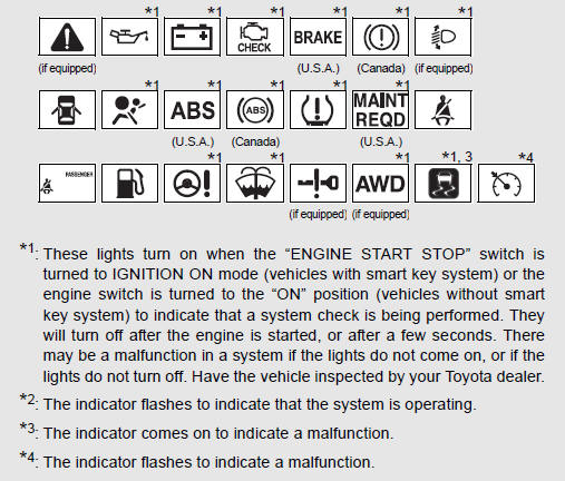
CAUTION
- If a safety system warning light does not come on
Should a safety system light such as the ABS and the SRS airbag warning lights not come on when you start the engine, this could mean that these systems are not available to help protect you in an accident, which could result in death or serious injury. Have the vehicle inspected by your Toyota dealer immediately if this occurs.
 Gauges and meters
►Vehicles with smart key system
The following gauges, meters and display illuminate when the “ENGINE START STOP”
switch is in IGNITION ON mode.
►Vehicles without smart key system ...
 Multi-information display (TFT type)
The multi-information display presents the driver with a variety of driving-related
data, including the clock and current outside temperature.
• Clock
Indicates and sets the time.
• Outside ...
Other materials about Toyota Venza:
Diagnostic Trouble Code Chart
DIAGNOSTIC TROUBLE CODE CHART
HINT:
If a DTC is displayed during the DTC check, check the parts listed in
the table below and proceed to the "See page" given.
If multiple suspected areas are listed, the potential causes of the
s ...
Inspection
INSPECTION
PROCEDURE
1. INSPECT COURTESY LIGHT SWITCH
(a) Measure the resistance according to the value(s) in the table below.
Standard Resistance:
Tester Connection
Switch Condition
Specified Condition
...
Bleeding
BLEEDING
CAUTION / NOTICE / HINT
NOTICE:
Do not allow brake fluid to adhere to any painted surface such as the
vehicle body. If brake fluid leaks onto any painted surface, immediately
wash it off.
Before bleeding the brake system, confir ...

0.1234