Toyota Venza: Front Passenger Side Power Window does not Operate with Front Passenger Side Power Window Switch
DESCRIPTION
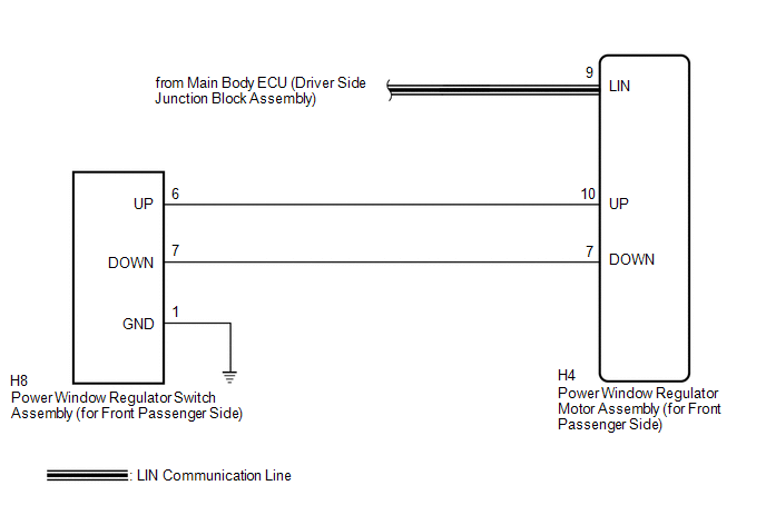
When the engine is running or the ignition switch is ON, the power window regulator motor assembly (for front passenger side) is operated by the power window regulator switch assembly (for front passenger side). The power window regulator motor assembly (for front passenger side) has motor, regulator, and ECU functions.
HINT:
If the pulse sensor built into the power window regulator motor assembly (for front passenger side) malfunctions, the power window control system enters fail-safe mode. The remote up/down and auto up/down functions cannot be operated during fail-safe mode. However, the power window can be closed by holding the power window regulator switch assembly (for front passenger side) at the auto up position, and opened manually by pushing down the power window regulator switch assembly (for front passenger side).
WIRING DIAGRAM
CAUTION / NOTICE / HINT
NOTICE:
- The power window control system uses a multiplex communication system
(LIN communication system). Inspect the communication function by following
How to Proceed with Troubleshooting (See page
.gif) ). Troubleshoot the power window control
). Troubleshoot the power window control
system after confirming that the communication system is functioning properly. - When the power window regulator motor assembly (for front passenger side) is reinstalled or replaced, the power window control system must be initialized.
- After a door glass or a door glass run has been replaced, the jam protection
function may operate unexpectedly when the auto up function is used. In
such cases, the auto up function can be reinitialized by repeating the following
operations at least 5 times:
- Close the power window by fully pulling up the power window regulator switch assembly (for front passenger side) and holding it at the auto up position.
- Open the power window by fully pushing down the power window regulator switch assembly (for front passenger side).
- When the ECU determines that the power window regulator motor assembly (for front passenger side) has a malfunction, DTC B2311 is set.
PROCEDURE
|
1. |
READ VALUE USING TECHSTREAM (Main Body) |
(a) Connect the Techstream to the DLC3.
(b) Turn the ignition switch to ON.
(c) Turn the Techstream on.
(d) Enter the following menus: Body Electrical / Main Body / Data List.
(e) Read the Data List according to the display on the Techstream.
Main Body (Main Body ECU (Driver Side Junction Block Assembly))|
Tester Display |
Measurement Item/Range |
Normal Condition |
Diagnostic Note |
|---|---|---|---|
|
Communication P-Door Motor |
Connection status between power window regulator motor (for front passenger side) and main body ECU (driver side junction block assembly) / OK or STOP |
OK: Normal communication STOP: Communication stopped |
- |
OK:
On the Techstream screen, OK is displayed.
| NG | .gif) |
GO TO LIN COMMUNICATION SYSTEM (Proceed to How to Proceed with Troubleshooting) |
|
.gif)
|
2. |
READ VALUE USING TECHSTREAM (P-Door Motor) |
(a) Enter the following menus: Body Electrical / P-Door Motor / Data List.
(b) Read the Data List according to the display on the Techstream.
P-Door Motor (Power Window Regulator Motor Assembly (for Front Passenger Side))|
Tester Display |
Measurement Item/Range |
Normal Condition |
Diagnostic Note |
|---|---|---|---|
|
P Door P/W Up SW |
Front passenger side power window manual up switch signal / ON or OFF |
ON: Front passenger door power window manual up switch operated OFF: Front passenger power window manual up switch not operated |
- |
|
P Door P/W Down SW |
Front passenger side power window manual down switch signal / ON or OFF |
ON: Front passenger door power window manual down switch operated OFF: Front passenger power window manual down switch not operated |
- |
OK:
On the Techstream screen, ON or OFF is displayed accordingly.
| NG | |
GO TO STEP 4 |
|
|
3. |
PERFORM ACTIVE TEST USING TECHSTREAM (P-Door Motor) |
(a) Enter the following menus: Body Electrical / P-Door Motor / Active Test.
(b) Perform the Active Test according to the display on the Techstream.
P-Door Motor (Power Window Regulator Motor Assembly (for Front Passenger Side))|
Tester Display |
Test Part |
Control Range |
Diagnostic Note |
|---|---|---|---|
|
Power Window |
Power window |
OFF / UP / DOWN |
- |
OK:
Front passenger side power window operates normally.
CAUTION:
Be careful to avoid injuries as this test causes vehicle parts to move. During the Active Test, the jam protection function will not operate.
| OK | |
REPLACE MAIN BODY ECU (DRIVER SIDE JUNCTION BLOCK ASSEMBLY) |
| NG | |
REPLACE POWER WINDOW REGULATOR MOTOR ASSEMBLY (for Front Passenger Side) |
|
4. |
INSPECT POWER WINDOW REGULATOR SWITCH ASSEMBLY (for Front Passenger Side) |
|
(a) Remove the power window regulator switch assembly (for front passenger
side) (See page |
|
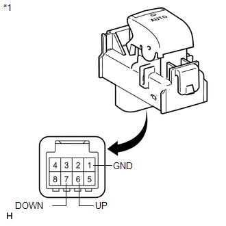
(b) Measure the resistance according to the value(s) in the table below.
Standard Resistance:
|
Tester Connection |
Condition |
Specified Condition |
|---|---|---|
|
6 (UP) - 1 (GND) |
Auto up or up position |
Below 1 Ω |
|
7 (DOWN) - 1 (GND) |
Auto down or down position |
Below 1 Ω |
|
*1 |
Component without harness connected (Power Window Regulator Switch Assembly (for Front Passenger Side)) |
| NG | |
REPLACE POWER WINDOW REGULATOR SWITCH ASSEMBLY (for Front Passenger Side) |
|
|
5. |
CHECK HARNESS AND CONNECTOR (FRONT PASSENGER SIDE SWITCH - MOTOR AND BODY GROUND) |
|
(a) Disconnect the power window regulator motor assembly (for front passenger side) connector. |
|
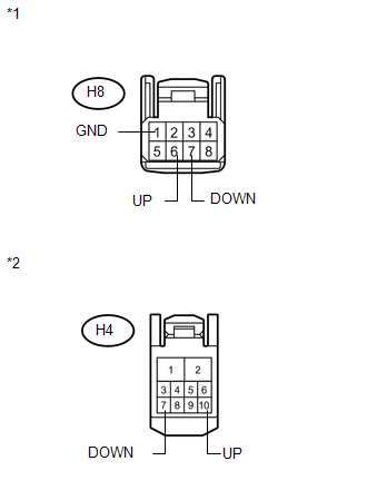
(b) Measure the resistance according to the value(s) in the table below.
Standard Resistance:
|
Tester Connection |
Condition |
Specified Condition |
|---|---|---|
|
H8-6 (UP) - H4-10 (UP) |
Always |
Below 1 Ω |
|
H8-7 (DOWN) - H4-7 (DOWN) |
Always |
Below 1 Ω |
|
H8-1 (GND) - Body ground |
Always |
Below 1 Ω |
|
H8-6 (UP) - Body ground |
Always |
10 kΩ or higher |
|
H8-7 (DOWN) - Body ground |
Always |
10 kΩ or higher |
|
H4-10 (UP) - Body ground |
Always |
10 kΩ or higher |
|
H4-7 (DOWN) - Body ground |
Always |
10 kΩ or higher |
|
*1 |
Front view of wire harness connector (to Power Window Regulator Switch Assembly (for Front Passenger Side)) |
|
*2 |
Front view of wire harness connector (to Power Window Regulator Motor Assembly (for Front Passenger Side)) |
| OK | |
REPLACE POWER WINDOW REGULATOR MOTOR ASSEMBLY (for Front Passenger Side) |
| NG | |
REPAIR OR REPLACE HARNESS OR CONNECTOR |
 Driver Side Power Window does not Operate with Power Window Master Switch
DESCRIPTION
When the engine is running or the ignition switch is ON, the power window regulator
motor assembly (for driver side) is operated by the power window regulator master
switch assembly. ...
 Rear Power Window LH does not Operate with Rear Power Window Switch LH
DESCRIPTION
When the engine is running or the ignition switch is ON, the power window regulator
motor assembly (for rear LH side) is operated by the power window regulator switch
assembly (for re ...
Other materials about Toyota Venza:
Diagnostic Trouble Code Chart
DIAGNOSTIC TROUBLE CODE CHART
HINT:
Parameters listed in the chart may not be exactly the same as your readings due
to the type of instrument or other factors. If a trouble code is displayed during
the DTC check, inspect the trouble areas listed for that ...
PBD Pulse Sensor Malfunction (B2222)
DESCRIPTION
A pulse sensor is built into the power back door ECU (power back door
motor unit) to detect foreign objects and the back door position. The pulse
sensor monitors the operating speed of the back door to detect foreign objects.
Th ...
Panel Switches do not Function
PROCEDURE
1.
CHECK PANEL SWITCH
(a) Check for foreign matter around the switches that might prevent operation.
OK:
No foreign matter is found.
NG
REMOVE ANY FOREIGN MATTER FOUND
...

0.1234