Toyota Venza: Idle Control System Malfunction (P0505)
DESCRIPTION
The idle speed is controlled by the electronic throttle control system. The electronic throttle control system is comprised of: 1) the one-valve-type throttle body; 2) the throttle actuator, which operates the throttle valve; 3) the throttle position sensor, which detects the opening angle of the throttle valve; 4) the accelerator pedal position sensor, which detects the accelerator pedal position; and 5) the ECM, which controls the electronic throttle control system. Based on the target idle speed, the ECM controls the throttle actuator to provide the proper throttle valve opening angle.
|
DTC No. |
DTC Detection Condition |
Trouble Area |
|---|---|---|
|
P0505 |
The idle speed continues to vary greatly from the target idle speed (2 trip detection logic). |
|
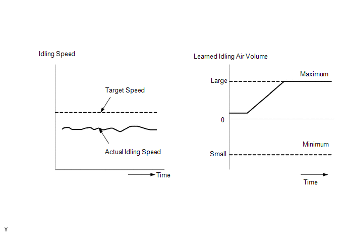
MONITOR DESCRIPTION
The ECM monitors the idling speed and idling air flow volume to conduct Idle Speed Control (ISC). The ECM determines that the ISC system is malfunctioning if either of the following conditions is met:
- The difference between the target engine idling speed and actual engine idling speed exceeds the threshold and the IAC flow rate learned value is stuck at the upper or lower limit for 5 seconds or more.
- After driving at a vehicle speed of 10 km/h (6.25 mph) or more, the
difference between the target and actual engine idling speed exceeds the
threshold 5 times or more during a driving cycle, and then the system determines
that the IAC flow rate learned value is stuck at the upper or lower limit,
or that the IAC flow rate learned value has been changed by an amount that
exceeds the threshold.
MONITOR STRATEGY
|
Related DTCs |
P0505: Idle Speed Control Function |
|
Required Sensors/Components (Main) |
Electronic throttle control system |
|
Required Sensors/Components (Related) |
Crankshaft position sensor Engine coolant temperature sensor Vehicle speed sensor |
|
Frequency of Operation |
Once per driving cycle |
|
Duration |
5 seconds |
|
MIL Operation |
2 driving cycles |
|
Sequence of Operation |
None |
TYPICAL ENABLING CONDITIONS
|
Monitor runs whenever following DTCs not stored |
P0010 (Camshaft Timing Oil Control Valve) P0011 (VVT System - Advance) P0012 (VVT System - Retard) P0016 (VVT System - Misalignment) P0013 (Exhaust Camshaft Timing Oil Control Valve) P0014 (Exhaust VVT System - Advance) P0015 (Exhaust VVT System - Retard) P0017 (Exhaust VVT System - Misalignment) P0031, P0032, P101D (Air Fuel Ratio Sensor Heater) P014C, P014D, P015A, P015B, P2195, P2196, P2237, P2238, P2239, P2252, P2253 (Air Fuel Ratio Sensor) P0102, P0103 (Mass Air Flow Meter) P0115, P0117, P0118 (Engine Coolant Temperature Sensor) P0125 (Insufficient Coolant Temperature for Closed Loop Fuel Control) P0120, P0121, P0122, P0123, P0220, P0222, P0223, P2135 (Throttle Position Sensor) P0171, P0172 (Fuel System) P0300 - P0304 (Misfire) P0335 (Crankshaft Position Sensor) P0340, P0342, P0343 (Camshaft Position Sensor) P0365, P0367, P0368 (Exhaust Camshaft Position Sensor) P0351 - P0354 (Igniter) P0451, P0452, P0453 (EVAP System) P0500 (Vehicle Speed Sensor) P0705 (Shift Lever Position Switch) P219A, P219C, P219D, P219E, P219F (Air Fuel Ratio Imbalance) |
|
Engine |
Running |
TYPICAL MALFUNCTION THRESHOLDS
|
Either of following conditions is met: |
Condition 1 or 2 |
|
1. Both of following conditions A and B met |
- |
|
A. Engine speed - Target engine speed |
Less than -100 rpm, or more than 150 rpm (A/C off and NSW off) Less than -100 rpm, or more than 200 rpm (A/C on or NSW on) |
|
B. IAC flow rate learned value |
0.9 L/sec. or less, or 6 L/sec. or more for 5 seconds |
|
2. Both of following conditions C and D met |
- |
|
C. Frequency that both of following conditions (a) and (b) met |
5 times or more |
|
(a) Engine speed - Target engine speed |
Less than -100 rpm, or more than 150 rpm (A/C off and NSW off) Less than -100 rpm, or more than 200 rpm (A/C on or NSW on) |
|
(b) Vehicle condition |
Stop after vehicle was driven by 10 km/h (6.25 mph) or more |
|
D. Either of following conditions is met |
Condition (c) or (d) |
|
(c) IAC flow rate learned value |
0.9 L/sec. or less, or 6 L/sec. or more |
|
(d) Amount of change of IAC flow rate learned value |
+2.56 L/sec. or more, or -2.56 L/sec. or less |
CONFIRMATION DRIVING PATTERN
- Connect the Techstream to the DLC3.
- Turn the ignition switch to ON and turn the Techstream on.
- Clear the DTCs (even if no DTCs are stored, perform the clear DTC operation)
(See page
.gif) ).
). - Turn the ignition switch off and wait for at least 30 seconds.
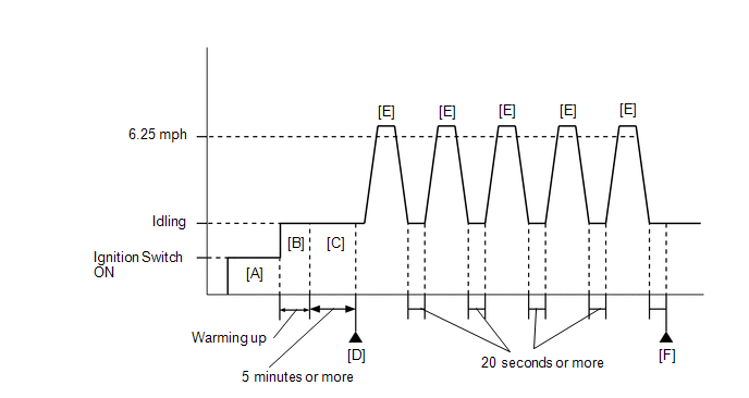
- Turn the ignition switch to ON and turn the Techstream on [A].
- Start the engine and warm it up until the engine coolant temperature is 75°C (167°F) or higher with all the accessories switched off [B].
- Idle the engine for 5 minutes or more [C].
HINT:
In order to keep the idling stable, turn off the A/C and all other electric loads and do not perform any shift operations.
- Enter the following menus: Powertrain / Engine / Trouble Codes [D].
- Read the pending DTCs.
HINT:
- If a pending DTC is output, the system is malfunctioning.
- If a pending DTC is not output, perform the following procedure.
- Enter the following menus: Powertrain / Engine / Utility / All Readiness.
- Input the DTC: P0505.
- Check the DTC judgment result.
Techstream Display
Description
NORMAL
- DTC judgment completed
- System normal
ABNORMAL
- DTC judgment completed
- System abnormal
INCOMPLETE
- DTC judgment not completed
- Perform driving pattern after confirming DTC enabling conditions
N/A
- Unable to perform DTC judgment
- Number of DTCs which do not fulfill DTC preconditions has reached ECU memory limit
HINT:
- If the judgment result shows NORMAL, the system is normal.
- If the judgment result shows ABNORMAL, the system has a malfunction.
- If the judgment result shows INCOMPLETE or N/A, perform steps [E] and [F].
- Accelerate the vehicle to 10 km/h (6.25 mph) or more, and then idle
the engine for 20 seconds or more [E].
CAUTION:
When performing the confirmation driving pattern, obey all speed limits and traffic laws.
- Repeat step [E] 5 times.
- Enter the following menus: Powertrain / Engine / Trouble Codes [F].
- Read the pending DTCs.
HINT:
- If a pending DTC is output, the system is malfunctioning.
- If a pending DTC is not output, perform the following procedure.
- Enter the following menus: Powertrain / Engine / Utility / All Readiness.
- Input the DTC: P0505.
- Check the DTC judgment result.
Techstream Display
Description
NORMAL
- DTC judgment completed
- System normal
ABNORMAL
- DTC judgment completed
- System abnormal
INCOMPLETE
- DTC judgment not completed
- Perform driving pattern after confirming DTC enabling conditions
N/A
- Unable to perform DTC judgment
- Number of DTCs which do not fulfill DTC preconditions has reached ECU memory limit
HINT:
- If the judgment result shows NORMAL, the system is normal.
- If the judgment result shows ABNORMAL, the system has a malfunction.
- If the judgment result is INCOMPLETE or N/A and no pending DTC is output,
perform a universal trip and check for permanent DTCs (See page
).
HINT:
- If a permanent DTC is output, the system is malfunctioning.
- If no permanent DTC is output, the system is normal.
CAUTION / NOTICE / HINT
HINT:
- The following conditions may also cause DTC P0505 to be stored:
- The floor carpet overlapping slightly onto the accelerator pedal, causing the accelerator pedal to be slightly depressed and therefore the throttle valve position to be slightly open.
- The accelerator pedal being not fully released.
- Read freeze frame data using the Techstream. The ECM records vehicle and driving condition information as freeze frame data the moment a DTC is stored. When troubleshooting, freeze frame data can help determine if the vehicle was moving or stationary, if the engine was warmed up or not, if the air fuel ratio was lean or rich, and other data from the time the malfunction occurred.
PROCEDURE
|
1. |
CHECK ANY OTHER DTCS OUTPUT (IN ADDITION TO DTC P0505) |
(a) Connect the Techstream to the DLC3.
(b) Turn the ignition switch to ON.
(c) Turn the Techstream on.
(d) Enter the following menus: Powertrain / Engine / Trouble Codes.
(e) Read the DTCs.
|
Result |
Proceed to |
|---|---|
|
DTC P0505 is output |
A |
|
DTC P0505 and other DTCs are output |
B |
HINT:
If any DTCs other than P0505 are output, troubleshoot those DTCs first.
| B | .gif) |
GO TO DTC CHART |
|
.gif)
|
2. |
CHECK PCV HOSE CONNECTIONS |
(a) Check the PCV hose connections (See page
).
OK:
PCV hose is connected correctly and is not damaged.
| NG | |
REPAIR OR REPLACE PCV HOSE |
|
|
3. |
CHECK INTAKE SYSTEM |
(a) Check the intake system for vacuum leakage (See page
).
OK:
No leakage from the intake system.
HINT:
Perform "Inspection After Repair" after repairing or replacing the intake system
(See page ).
| NG | |
REPAIR OR REPLACE INTAKE SYSTEM |
|
|
4. |
INSPECT THROTTLE BODY (THROTTLE VALVE) |
(a) Check the throttle valve condition.
OK:
Throttle valve is not contaminated with foreign objects and moves smoothly.
HINT:
Perform "Inspection After Repair" after replacing the throttle body (See page
).
| NG | |
REPLACE THROTTLE BODY |
|
|
5. |
CHECK WHETHER DTC OUTPUT RECURS (DTC P0505) |
(a) Connect the Techstream to the DLC3.
(b) Turn the ignition switch to ON.
(c) Turn the Techstream on.
(d) Clear the DTCs.
(e) Turn the ignition switch off and wait for at least 30 seconds.
(f) Turn the ignition switch to ON.
(g) Turn the Techstream on.
(h) Drive the vehicle in accordance with the driving pattern described in Confirmation Driving Pattern.
(i) Enter the following menus: Powertrain / Engine / Trouble Codes.
(j) Read the DTCs.
Result|
Result |
Proceed to |
|---|---|
|
DTC P0505 is output |
A |
|
DTC is not output |
B |
| A | |
REPLACE ECM |
| B | |
END |
 Brake Switch "A" / "B" Correlation (P0504)
DESCRIPTION
The stop light switch is a duplex system that transmits 2 signals: STP and ST1-.
These 2 signals are used by the ECM to monitor whether or not the brake system is
working properly. If ...
 Cold Start Idle Air Control System Performance (P050A)
MONITOR DESCRIPTION
This monitor will run when the engine is started at an engine coolant temperature
of -10 to 50°C (14 to 122°F). The DTC is stored after the engine idles for 13
seconds (2 tr ...
Other materials about Toyota Venza:
System Description
SYSTEM DESCRIPTION
1. SYSTEM DESCRIPTION
(a) The Electronic Controlled Automatic Transaxle (ECT) is an automatic transaxle
that has its shift timing electronically controlled by the Transmission Control
Module (TCM). The TCM detects electrical signals th ...
Replacement
REPLACEMENT
CAUTION / NOTICE / HINT
NOTICE:
Move the shift lever to P and apply the parking brake before bleeding
the brakes.
Add brake fluid to keep the level between the MIN and MAX lines of the
reservoir while bleeding the brakes.
...
Room Oscillator does not Recognize Key
DESCRIPTION
If the room oscillator does not recognize a key, one of the following may be
the cause: 1) communication between the indoor electrical key oscillator (for front
floor) and key cannot be performed; 2) communication between the indoor electrical ...

0.1546