Toyota Venza: Front Stabilizer Bar(for 2gr-fe 2wd)
Components
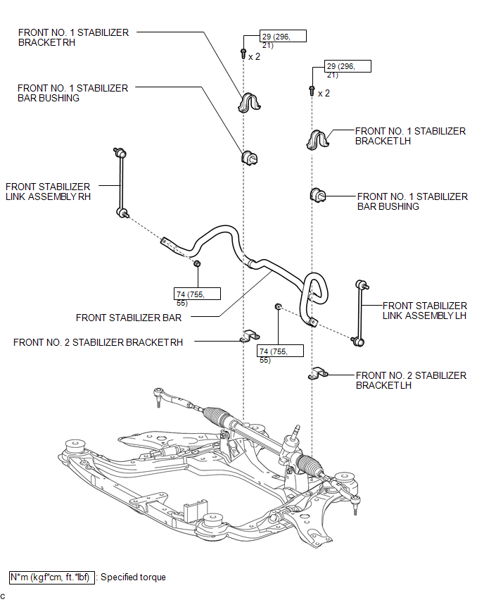
COMPONENTS
ILLUSTRATION
Removal
REMOVAL
PROCEDURE
1. REMOVE FRONT FRAME ASSEMBLY (When Using the Engine Support Bridge)
(See page .gif) )
)
2. REMOVE ENGINE ASSEMBLY WITH TRANSAXLE (When Not Using the Engine Support Bridge)
(See page )
3. SEPARATE FRONT STABILIZER LINK ASSEMBLY LH
|
(a) Remove the nut and separate the front stabilizer link assembly LH. HINT: If the ball joint turns together with the nut, use a hexagon wrench (6 mm) to hold the stud bolt. |
|
.png)
4. SEPARATE FRONT STABILIZER LINK ASSEMBLY RH
HINT:
Perform the same procedure as for the LH side.
5. REMOVE FRONT NO. 1 STABILIZER BRACKET LH
|
(a) Remove the 2 bolts and front No. 1 stabilizer bracket LH from the front frame assembly. |
|
.png)
6. REMOVE FRONT NO. 1 STABILIZER BRACKET RH
HINT:
Perform the same procedure as for the LH side.
7. REMOVE FRONT STABILIZER BAR
(a) Remove the front stabilizer bar from the front frame assembly.
8. REMOVE FRONT NO. 2 STABILIZER BRACKET LH
|
(a) Remove the front No. 2 stabilizer bracket LH from the front No. 1 stabilizer bar bushing. |
|
.png)
9. REMOVE FRONT NO. 2 STABILIZER BRACKET RH
HINT:
Perform the same procedure as for the LH side.
10. REMOVE FRONT NO. 1 STABILIZER BAR BUSHING
(a) Remove the 2 front No. 1 stabilizer bar bushings from the front stabilizer bar.
Inspection
INSPECTION
PROCEDURE
1. INSPECT FRONT STABILIZER LINK ASSEMBLY
|
(a) Inspect the turning torque of the ball joint. (1) Secure the front stabilizer link assembly in a vise using aluminum plates. (2) Install the nut to the front stabilizer link assembly stud. (3) Using a torque wrench, turn the nut continuously at a rate of 3 to 5 seconds per turn and take the torque reading on the 5th turn. Turning torque: 0.05 to 1.96 N*m (0.5 to 20 kgf*cm, 0.4 to 17 in.*lbf) If the turning torque is not within the specified range, replace the front stabilizer link assembly with a new one. |
|
.png)
(b) Inspect the dust cover.
(1) Check that the dust cover is not cracked and that there is no grease on it.
Installation
INSTALLATION
PROCEDURE
1. INSTALL FRONT NO. 1 STABILIZER BAR BUSHING
|
(a) Install the 2 front No. 1 stabilizer bar bushings to the front stabilizer bar as shown in the illustration. Text in Illustration
NOTICE: When installing the front No. 1 stabilizer bar bushings, make sure that the cutout faces the rear of the vehicle. |
|
.png)
2. INSTALL FRONT NO. 2 STABILIZER BRACKET LH
|
(a) Install the front No. 2 stabilizer bracket LH to the front No. 1 stabilizer bar bushing. |
|
.png)
3. INSTALL FRONT NO. 2 STABILIZER BRACKET RH
HINT:
Perform the same procedure as for the LH side.
4. INSTALL FRONT STABILIZER BAR
(a) Install the front stabilizer bar to the front frame assembly.
5. INSTALL FRONT NO. 1 STABILIZER BRACKET LH
|
(a) Install the front No. 1 stabilizer bracket LH to the front frame assembly with the 2 bolts. Torque: 29 N·m {296 kgf·cm, 21 ft·lbf} |
|
.png)
6. INSTALL FRONT NO. 1 STABILIZER BRACKET RH
HINT:
Perform the same procedure as for the LH side.
7. INSTALL FRONT STABILIZER LINK ASSEMBLY LH
|
(a) Install the front stabilizer link assembly LH with the nut. Torque: 74 N·m {755 kgf·cm, 55 ft·lbf} HINT: If the ball joint turns together with the nut, use a hexagon wrench (6 mm) to hold the stud bolt. |
|
.png)
8. INSTALL FRONT STABILIZER LINK ASSEMBLY RH
HINT:
Perform the same procedure as for the LH side.
9. INSTALL FRONT FRAME ASSEMBLY (When Using the Engine Support Bridge)
(See page .gif) )
)
10. INSTALL ENGINE ASSEMBLY WITH TRANSAXLE (When Not Using the Engine Support Bridge)
(See page )
 Front Stabilizer Bar(for 1ar-fe 2wd)
Components
COMPONENTS
ILLUSTRATION
Inspection
INSPECTION
PROCEDURE
1. INSPECT FRONT STABILIZER LINK ASSEMBLY
(a) Inspect the turning torque of the ball joint.
(1) Secure the ...

Other materials about Toyota Venza:
Locking the driver’s doors from the outside without a key
Move the inside lock button to the
lock position.
Close the door.
►Vehicles with smart key system
The door cannot be locked if the “ENGINE START STOP” switch is in ACCESSORY or IGNITION
ON mode, or the electronic key is left inside the vehic ...
Disassembly
DISASSEMBLY
CAUTION / NOTICE / HINT
NOTICE:
When disassembling the multiplex network door ECU, eliminate static electricity
by touching the vehicle body to prevent the components from being damaged.
PROCEDURE
1. REMOVE MULTIPLEX NETWORK DOOR ECU
...
Front Passenger Side Door Entry Lock Function does not Operate
DESCRIPTION
If the front passenger door entry unlock function operates normally, but its
entry lock function does not, this means that the request code from the front passenger
door is being output normally. In this case, a malfunction in the lock sensor ...

0.1587