Toyota Venza: Removal
REMOVAL
PROCEDURE
1. REMOVE UPPER CONSOLE PANEL SUB-ASSEMBLY (w/o Seat Heater System)
.gif)
2. REMOVE UPPER CONSOLE PANEL SUB-ASSEMBLY (w/ Seat Heater System)
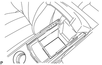
3. REMOVE NO. 2 CONSOLE BOX CARPET
|
(a) Remove the No. 2 console box carpet. |
|
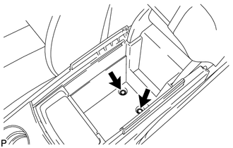
4. REMOVE CONSOLE BOX ASSEMBLY
|
(a) Remove the 2 bolts. |
|
|
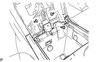
(b) Remove the screw and 2 clips. |
|
|
(c) Disengage the 2 claws. |
|
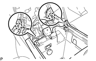
(d) Disconnect the connectors and remove the console box assembly.
 Disassembly
DISASSEMBLY
PROCEDURE
1. REMOVE NO. 1 CONSOLE BOX CARPET
(a) Remove the No. 1 console box carpet.
2. REMOVE INSTRUMENT PANEL CUP HOLDER DA ...
 Installation
INSTALLATION
PROCEDURE
1. INSTALL CONSOLE BOX ASSEMBLY
(a) Connect the connectors.
(b) Engage the 2 claws.
(c) Install the scr ...
Other materials about Toyota Venza:
VSC OFF Indicator Light does not Come ON
DESCRIPTION
The skid control ECU is connected to the combination meter via CAN communication.
WIRING DIAGRAM
Refer to VSC OFF Indicator Light Remains ON (See page
).
PROCEDURE
1.
CHECK CAN COMMUNICATION SYSTEM
(a) Check ...
On-vehicle Inspection
ON-VEHICLE INSPECTION
PROCEDURE
1. INSPECT CENTER AIRBAG SENSOR ASSEMBLY (VEHICLE NOT INVOLVED IN COLLISION)
(a) Perform a diagnostic system check (See page
).
2. INSPECT CENTER AIRBAG SENSOR ASSEMBLY (VEHICLE INVOLVED IN COLLISION AND AIRBAG
HAS NOT D ...
Installation
INSTALLATION
PROCEDURE
1. INSTALL FRONT SHOULDER BELT ANCHOR ADJUSTER ASSEMBLY
(a) Engage the adjuster positioning hole with the guide and install the
front shoulder belt anchor adjuster assembly with the 2 bolts.
Torque:
42 N·m {428 ...

0.1169