Toyota Venza: Removal
REMOVAL
PROCEDURE
1. PRECAUTION (w/ Navigation System)
NOTICE:
After turning the ignition switch off, waiting time may be required before disconnecting
the cable from the negative (-) battery terminal. Therefore, make sure to read the
disconnecting the cable from the negative (-) battery terminal notices before proceeding
with work (See page .gif) ).
).
2. DISCONNECT CABLE FROM NEGATIVE BATTERY TERMINAL (w/ Navigation System)
NOTICE:
When disconnecting the cable, some systems need to be initialized after the cable
is reconnected (See page ).
3. REMOVE UPPER CONSOLE PANEL SUB-ASSEMBLY (w/o Seat Heater System)
4. REMOVE UPPER CONSOLE PANEL SUB-ASSEMBLY (w/ Seat Heater System)
5. REMOVE NO. 2 CONSOLE BOX CARPET
6. REMOVE CONSOLE BOX ASSEMBLY
7. REMOVE AIR CONDITIONING CONTROL ASSEMBLY
8. REMOVE FRONT DOOR SCUFF PLATE RH
9. REMOVE COWL SIDE TRIM SUB-ASSEMBLY RH
10. REMOVE NO. 2 INSTRUMENT PANEL UNDER COVER SUB-ASSEMBLY
11. REMOVE LOWER INSTRUMENT PANEL SUB-ASSEMBLY
12. REMOVE SHIFT LEVER KNOB SUB-ASSEMBLY
13. REMOVE POSITION INDICATOR HOUSING ASSEMBLY
14. REMOVE CONSOLE BOX SUB-ASSEMBLY
15. REMOVE NO. 2 INSTRUMENT PANEL SPEAKER PANEL SUB-ASSEMBLY
16. REMOVE RADIO AND DISPLAY RECEIVER ASSEMBLY WITH BRACKET (w/o Navigation System)
17. REMOVE NAVIGATION RECEIVER ASSEMBLY WITH BRACKET (w/ Navigation System)
18. REMOVE INSTRUMENT CLUSTER CENTER FINISH PANEL SUB-ASSEMBLY (w/o Navigation System)
19. REMOVE INSTRUMENT CLUSTER CENTER FINISH PANEL SUB-ASSEMBLY (w/ Navigation System)
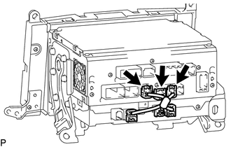
20. REMOVE STEREO COMPONENT TUNER ASSEMBLY WITH WIRE
|
(a) Disconnect the 3 connectors. |
|
|
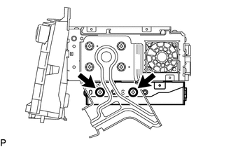
(b) Remove the 2 screws. |
|
|
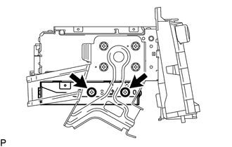
(c) Remove the 2 screws and stereo component tuner assembly with wire. |
|
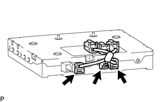
21. REMOVE NAVIGATION WIRE
|
(a) Disconnect the 3 connectors to remove the navigation wire. |
|
22. REMOVE STEREO COMPONENT TUNER ASSEMBLY
 Components
COMPONENTS
ILLUSTRATION
ILLUSTRATION
ILLUSTRATION
...
 Installation
INSTALLATION
PROCEDURE
1. INSTALL STEREO COMPONENT TUNER ASSEMBLY
2. INSTALL NAVIGATION WIRE
(a) Connect the 3 connectors to install the navigation wire.
3. INSTALL STEREO COMPONENT TUNER ASSEMBL ...
Other materials about Toyota Venza:
Installation
INSTALLATION
PROCEDURE
1. INSTALL INSTRUMENT PANEL WIRE ASSEMBLY
(a) Connect the vent hole connector of the instrument panel wire to the
front passenger airbag assembly.
Text in Illustration
*1
Vent Hol ...
CD cannot be Ejected
PROCEDURE
1.
CHECK OPERATION
(a) Press the disc eject switch of the radio and display receiver assembly for
5 seconds or more and check that the CD is ejected.
OK:
CD is ejected.
NG
REPLACE RADIO AND D ...
Trailer Tongue Weight
• A recommended tongue weight varies in accordance with the types of trailers
or towing as described below.
• To ensure the recommended values shown below, the trailer must be loaded by
referring to the following instructions.
• Tongue Weight The g ...

0.1453