Toyota Venza: Engine Hood Courtesy Switch
Components
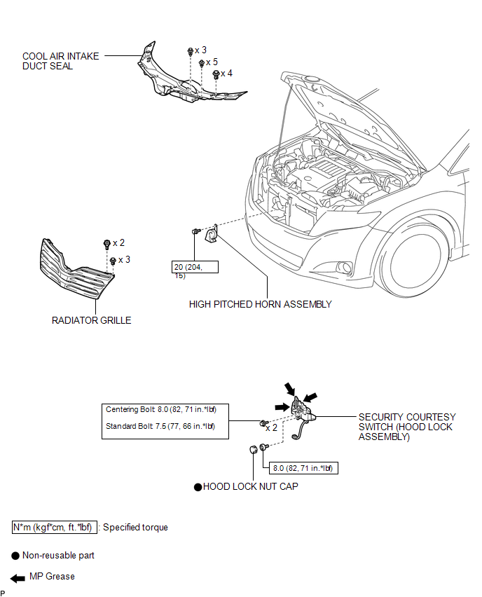
COMPONENTS
ILLUSTRATION
Inspection
INSPECTION
PROCEDURE
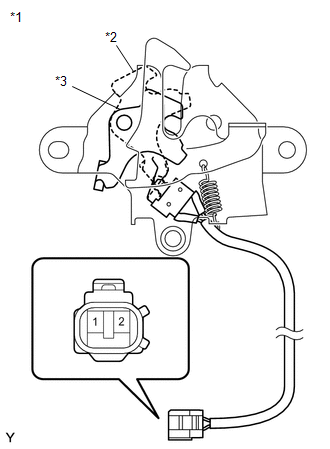
1. INSPECT SECURITY COURTESY SWITCH (HOOD LOCK ASSEMBLY)
|
(a) Measure the resistance according to the value(s) in the table below. Standard Resistance:
If the result is not as specified, replace the security courtesy switch (hood lock assembly). |
|
Removal
REMOVAL
PROCEDURE
1. REMOVE COOL AIR INTAKE DUCT SEAL
.gif)
2. REMOVE RADIATOR GRILLE
3. REMOVE HIGH PITCHED HORN ASSEMBLY
4. REMOVE SECURITY COURTESY SWITCH (HOOD LOCK ASSEMBLY)
Installation
INSTALLATION
PROCEDURE
1. INSTALL SECURITY COURTESY SWITCH (HOOD LOCK ASSEMBLY)
.gif)
2. INSTALL HIGH PITCHED HORN ASSEMBLY
3. INSTALL RADIATOR GRILLE
4. INSTALL COOL AIR INTAKE DUCT SEAL
5. INSPECT HOOD SUB-ASSEMBLY
6. ADJUST HOOD SUB-ASSEMBLY
 Electrical Key Oscillator(for Rear Side)
Components
COMPONENTS
ILLUSTRATION
Removal
REMOVAL
PROCEDURE
1. REMOVE REAR BUMPER PLATE LH
2. REMOVE REAR BUMPER PLATE RH
3. REMOVE REAR BUMPER ASSEMBLY
4. REMOVE ELECTRICAL K ...

Other materials about Toyota Venza:
Components
COMPONENTS
ILLUSTRATION
ILLUSTRATION
ILLUSTRATION
ILLUSTRATION
ILLUSTRATION
ILLUSTRATION
...
Customizing the features by using the multi-information display (vehicles with
TFT type multi-information display)
Press the “SETUP” button while the vehicle is stopped.
The “Custom Settings” screen is displayed on the multi-information display.
If left idle for approximately 10 seconds, the display will revert to the previous
screen.
Select the setting yo ...
Reassembly
REASSEMBLY
PROCEDURE
1. INSTALL COOLER DRYER
(a) Using pliers, install a new cooler dryer to the modulator.
(b) Apply sufficient compressor oil to the O-ring and fitting surfaces
of t ...

0.1302