Toyota Venza: Adjustment
ADJUSTMENT
PROCEDURE
1. INSPECT TIRES
(a) Inspect the tires (See page .gif) ).
).
2. MEASURE VEHICLE HEIGHT
NOTICE:
- Before inspecting the wheel alignment, adjust the vehicle height to the specified value.
- Be sure to perform measurement on a level surface.
- If it is necessary to go under the vehicle for measurement, confirm that the parking brake is applied and the vehicle is secured with chocks.
(a) Bounce the vehicle up and down at the corners to stabilize the suspension.
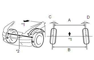
(b) Measure the vehicle height.
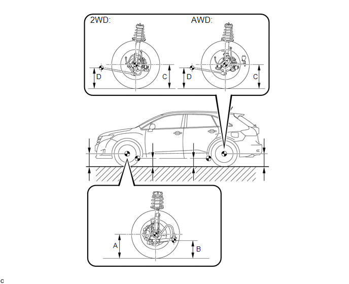
Measurement points:
A
Ground clearance of front wheel center
B
Ground clearance of No. 2 lower suspension arm bushing set bolt center
C
Ground clearance of rear wheel center
D
Ground clearance of strut rod set bolt center
Vehicle Height (Unloaded Vehicle):
|
Engine |
Model |
Front A - B |
Rear C - D |
|---|---|---|---|
|
1AR-FE |
2WD |
116.4 mm (4.582 in.) |
33.9 mm (1.335 in.) |
|
AWD |
116.9 mm (4.602 in.) |
30.8 mm (1.213 in.) |
|
|
2GR-FE |
2WD |
117.7 mm (4.634 in.) |
31.0 mm (1.220 in.) |
|
AWD |
117.8 mm (4.638 in.) |
31.8 mm (1.252 in.) |
3. INSPECT CAMBER, CASTER AND STEERING AXIS INCLINATION
|
(a) Install a camber-caster-kingpin gauge and place the front wheels on the center of a wheel alignment tester. Text in Illustration
|
|
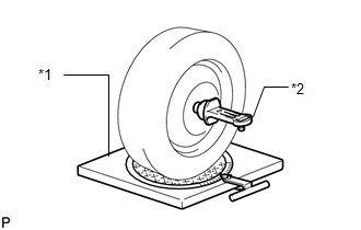
(b) Inspect the camber, caster and steering axis inclination.
Camber (Unloaded Vehicle):
|
Engine |
Model |
Camber Inclination |
Right-left Difference |
|---|---|---|---|
|
1AR-FE |
2WD |
-0°35' +/- 45' (-0.58° +/- 0.75°) |
45' (0.75°) or less |
|
AWD |
-0°36' +/- 45' (-0.60° +/- 0.75°) |
||
|
2GR-FE |
2WD |
-0°36' +/- 45' (-0.60° +/- 0.75°) |
45' (0.75°) or less |
|
AWD |
-0°36' +/- 45' (-0.60° +/- 0.75°) |
Caster (Unloaded Vehicle):
|
Engine |
Model |
Caster Inclination |
Right-left Difference |
|---|---|---|---|
|
1AR-FE |
2WD |
2°39' +/- 45' (2.65° +/- 0.75°) |
45' (0.75°) or less |
|
AWD |
2°41' +/- 45' (2.68° +/- 0.75°) |
||
|
2GR-FE |
2WD |
2°38' +/- 45' (2.63° +/- 0.75°) |
45' (0.75°) or less |
|
AWD |
2°40' +/- 45' (2.67° +/- 0.75°) |
Steering Axis Inclination (Unloaded Vehicle):
|
Engine |
Model |
Steering Axis Inclination |
|---|---|---|
|
1AR-FE |
2WD |
10°42' +/- 45' (10.70° +/- 0.75°) |
|
AWD |
10°42' +/- 45' (10.70° +/- 0.75°) |
|
|
2GR-FE |
2WD |
10°43' +/- 45' (10.72° +/- 0.75°) |
|
AWD |
10°43' +/- 45' (10.72° +/- 0.75°) |
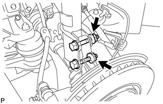
4. ADJUST CAMBER
NOTICE:
Inspect toe-in after the camber has been adjusted.
(a) Remove the front wheel.
|
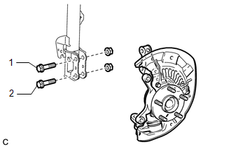
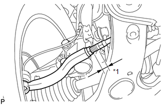
(b) Remove the 2 nuts on the lower side of the front shock absorber. NOTICE: Keep the bolts inserted. |
|
(c) Clean the installation surfaces of the front shock absorber and the steering knuckle.
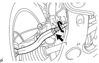
(d) Temporarily install the 2 nuts. (Step A)
|
(e) Fully push or pull the front axle hub in the direction of the required adjustment. (Step B) |
|
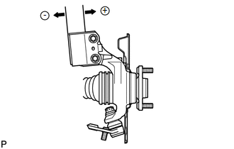
(f) Tighten the nuts.
Torque:
290 N·m {2956 kgf·cm, 214 ft·lbf}
NOTICE:
Keep the bolts from rotating when tightening the nuts.
(g) Install the front wheel.
Torque:
103 N·m {1050 kgf·cm, 76 ft·lbf}
(h) Check the camber.
Camber (Unloaded Vehicle):
|
Engine |
Model |
Camber Inclination |
Right-left Difference |
|---|---|---|---|
|
1AR-FE |
2WD |
-0°35' +/- 45' (-0.58° +/- 0.75°) |
45' (0.75°) or less |
|
AWD |
-0°36' +/- 45' (-0.60° +/- 0.75°) |
||
|
2GR-FE |
2WD |
-0°36' +/- 45' (-0.60° +/- 0.75°) |
45' (0.75°) or less |
|
AWD |
-0°36' +/- 45' (-0.60° +/- 0.75°) |
If the measured value is not within the specification, calculate the required adjustment amount using the formula below.
Camber adjustment amount = center value of the specified range - measured value
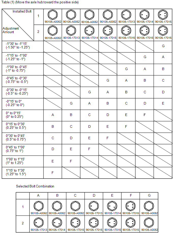
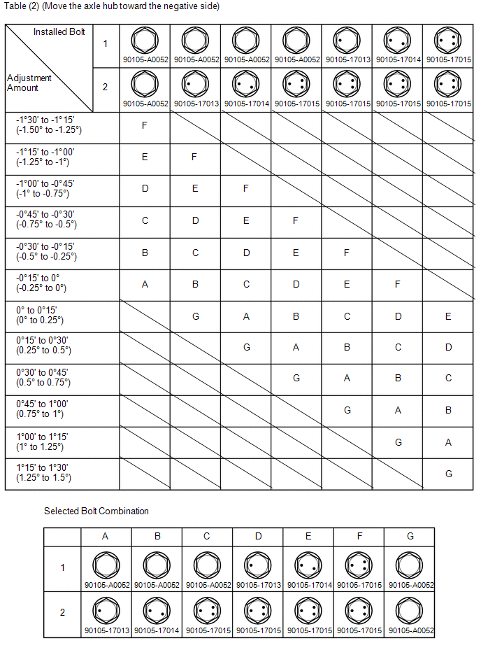
Check the combination of installed bolts. Select appropriate bolts from the table below to adjust the camber to the specified values.
HINT:
Try to adjust the camber to the center of the specified values.
|
Move the Axle Toward (+) in Step (B) |
Move the Axle Toward (-) in Step (B) |
|---|---|
|
Refer to table (1) (Move the axle toward the positive side) |
Refer to table (2) (Move the axle toward the negative side) |
The body and suspension may be damaged if the camber is not correctly adjusted according to the above table.
NOTICE:
Replace the nut with a new one when replacing the bolt.
(i) Repeat the steps mentioned above. In step (A), replace 1 or 2 selected bolts.
HINT:
Replace one bolt at a time when replacing 2 bolts.
5. INSPECT TOE-IN
(a) Bounce the vehicle up and down at the corners to stabilize the suspension.
(b) Release the parking brake and move the shift lever to N.
(c) Push the vehicle straight ahead approximately 5 m (16.4 ft.)*1.
|
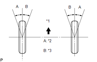
(d) Put tread center marks on the rearmost points of the front wheels and measure the distance between the marks (dimension B). Text in Illustration
|
|
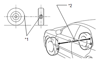
(e) Slowly push the vehicle straight ahead to cause the front wheels to rotate 180° using the front tire valve as a reference point.
HINT:
Do not allow the wheels to rotate more than 180°. If the wheels rotate more than 180°, perform the procedure from *1 again.
|
(f) Measure the distance between the tread center marks on the front side of the wheels (dimension A). Text in Illustration
Toe-in:
If the toe-in is not within the specified range, adjust it at the rack ends. HINT: Measure "B - A" only when "C + D" cannot be measured. |
|
6. ADJUST TOE-IN
|
(a) Make sure that the lengths of the right and left rack ends are almost the same. Text in Illustration
Standard difference: 1.5 mm (0.0591 in.) or less |
|
(b) Remove the rack boot set clips.
|
(c) Loosen the tie rod end lock nuts. Text in Illustration
|
|
(d) Adjust the rack ends if the difference in thread length between the right and left rack ends is not within the specified range.
(1) Extend the shorter rack end if the measured toe-in deviates toward the outside.
(2) Shorten the longer rack end if the measured toe-in deviates toward the inside.
(e) Turn the right and left rack ends by an equal amount to adjust the toe-in to the center value.
(f) Make sure that the lengths of the right and left rack ends are the same.
(g) Tighten the tie rod end lock nuts.
Torque:
88 N·m {897 kgf·cm, 65 ft·lbf}
NOTICE:
Temporarily tighten the lock nut while holding the hexagonal part of the steering rack end so that the lock nut and the steering rack end do not turn together. Hold the width across flat of the tie rod end and tighten the lock nut.
(h) Place the boots on the seats and install the clips.
HINT:
Make sure that the boots are not twisted.
7. INSPECT WHEEL ANGLE
(a) Put tread center marks on the rearmost points of the turning radius gauge.
|
(b) Turn the steering wheel to the left and right full lock positions, and measure the turning angle. Text in Illustration
Wheel Turning Angle (Unloaded Vehicle):
If the angles are not as specified, check and adjust the right and left rack end lengths. |
|
8. PLACE FRONT WHEELS FACING STRAIGHT AHEAD

 Rear Wheel Alignment
Adjustment
ADJUSTMENT
PROCEDURE
1. INSPECT TIRES
(a) Inspect the tires (See page ).
2. MEASURE VEHICLE HEIGHT
3. INSPECT CAMBER
Camber (Unloaded Vehicle):
Model
En ...
Other materials about Toyota Venza:
Intake Manifold Runner Control Circuit Low (Bank 1) (P2009,P2010)
DESCRIPTION
The ECM activates the DC motor for the tumble control valve, which opens and
closes the tumble control valve. The ECM activates the DC motor based on engine
speed, coolant temperature, intake air temperature and other conditions.
D ...
Removal
REMOVAL
CAUTION / NOTICE / HINT
NOTICE:
When disconnecting the steering intermediate shaft assembly and pinion shaft
of steering gear assembly, be sure to place matchmarks before servicing.
PROCEDURE
1. PLACE FRONT WHEELS FACING STRAIGHT AHEAD
2. SECUR ...
Touch Panel Switch does not Function
PROCEDURE
1.
CHECK MULTI-DISPLAY
(a) Check if there is any foreign matter caught between the display and exterior
frame of the multi-display.
OK:
No foreign matter is caught between the display and exterior frame of the m ...

0.1456