Toyota Venza: Customizing the features by using the multi-information display (vehicles with TFT type multi-information display)
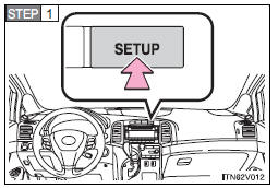
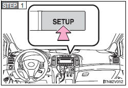
Press the “SETUP” button while the vehicle is stopped.
The “Custom Settings” screen is displayed on the multi-information display.
If left idle for approximately 10 seconds, the display will revert to the previous screen.
Select the setting you wish to change by pressing the “INFO” or “SETUP” button, and press the “SELECT RESET” button.
If you select “Exit” and press the “SELECT RESET” button, the display will revert to the previous screen.
Select the setting you wish to change by pressing the “INFO” or “SETUP” button, and press the “SELECT RESET” button.
The illustration assumes that “Door” was chosen in
 .
.
The current setting is indicated by yellow text.
If you select “Return” and press the “SELECT RESET” button, the display will revert to the “Custom Settings” screen.
Choose a desired setting by pressing the “INFO” or “SETUP” button, and press the “SELECT RESET” button.
If any settings are changed, the display will revert to the previous screen.
The illustration assumes that “Auto Locking” was chosen in
 .
.
The current setting is indicated by yellow text.
If you select “Return” and press the “SELECT RESET” button, the display will revert to the previous screen.
- Restoring default settings
Press the “SETUP” button while the vehicle is stopped.
The “Custom Settings” screen is displayed on the multi-information display.
If left idle for approximately 10 seconds, the display will revert to the previous screen.
Select “Default Settings” by pressing the “INFO” or “SETUP” button, and press the “SELECT RESET” button.
If you select “Exit” and press the “SELECT RESET” button, the display will revert to the previous screen.
Select “Yes” by pressing the “INFO” or “SETUP” button, and press the “SELECT RESET” button.
“Default Settings Restored” is displayed, and the default settings are restored.
If you select “No” and press the “SELECT RESET” button, the display will revert to the “Custom Settings” screen without restoring the default settings.
- If the vehicle is moved while settings are being changed on the multiinformation display
 Customizable features
1. Vehicles with TFT type multi-information display: Some function settings can
be changed by operating the multi-information display.
2. Settings that can be changed by your Toyota dealer
Definit ...
 Initialization
...
Other materials about Toyota Venza:
No Response from Steering Lock ECU (B2786)
DESCRIPTION
This DTC is stored when LIN communication between the certification ECU (smart
key ECU assembly) and steering lock ECU (steering lock actuator assembly) stops
for more than 10 seconds.
DTC No.
DTC Detection Condition
...
System Diagram
SYSTEM DIAGRAM
1. AUTOMATIC LIGHT CONTROL SYSTEM
2. LIGHT AUTO TURN-OFF SYSTEM
Communication Table
Transmitter
Receiver
Line
Data Name
Certification ECU (Smart Key ECU Assembly)
Mai ...
Rear Door LH ECU Communication Stop (B2324)
DESCRIPTION
This DTC is stored when LIN communication between the power window regulator
motor assembly (for rear LH side) and main body ECU (driver side junction block
assembly) stops for more than 10 seconds.
DTC No.
DTC Detection ...

0.1176