Toyota Venza: Evaporator Temperature Sensor Circuit (B1413/13)
DESCRIPTION
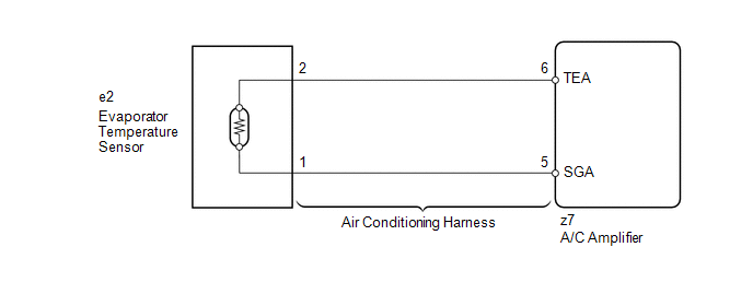
The evaporator temperature sensor is installed on the evaporator in the air conditioning unit to detect the cooled air temperature that has passed through the evaporator and to control the air conditioning. It sends appropriate signals to the A/C amplifier. The resistance of the evaporator temperature sensor changes in accordance with the cooled air temperature that has passed through the evaporator. As the temperature decreases, the resistance increases. As the temperature increases, the resistance decreases.
The A/C amplifier applies voltage (5 V) to the evaporator temperature sensor and reads voltage changes as the resistance of the evaporator temperature sensor changes. This sensor is used for frost prevention.
|
DTC No. |
DTC Detection Condition |
Trouble Area |
|---|---|---|
|
B1413/13 |
Open or short in evaporator temperature sensor circuit |
|
WIRING DIAGRAM
PROCEDURE
|
1. |
READ VALUE USING TECHSTREAM |
(a) Connect the Techstream to the DLC3.
(b) Turn the ignition switch to ON.
(c) Turn the Techstream on.
(d) Enter the following menus: Body / Air Conditioner / Data List.
(e) Check the value(s) by referring to the table below.
Air Conditioner|
Tester Display |
Measurement Item/Range |
Normal Condition |
Diagnostic Note |
|---|---|---|---|
|
Evaporator Fin Thermistor |
Evaporator temperature sensor / Min.: -30°C (-22°F) Max.: 59.6°C (139.28°F) |
Actual evaporator temperature displayed |
- |
OK:
The display is as specified in the Normal Condition column.
|
Result |
Proceed to |
|---|---|
|
NG |
A |
|
OK (When troubleshooting according to Problem Symptoms Table) |
B |
|
OK (When troubleshooting according to the DTC) |
C |
| B | .gif) |
PROCEED TO NEXT SUSPECTED AREA SHOWN IN PROBLEM SYMPTOMS TABLE |
| C | |
REPLACE A/C AMPLIFIER |
|
.gif)
|
2. |
INSPECT EVAPORATOR TEMPERATURE SENSOR |
(a) Remove the evaporator temperature sensor.
(b) Disconnect the evaporator temperature sensor connector.
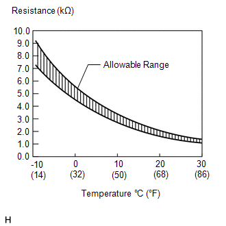
(c) Measure the resistance according to the value(s) in the table below.
Standard Resistance:
|
Tester Connection |
Condition |
Specified Condition |
|---|---|---|
|
e2-1 - e2-2 |
-10°C (14°F) |
7.30 to 9.10 kΩ |
|
e2-1 - e2-2 |
-5°C (23°F) |
5.65 to 6.95 kΩ |
|
e2-1 - e2-2 |
0°C (32°F) |
4.40 to 5.35 kΩ |
|
e2-1 - e2-2 |
5°C (41°F) |
3.40 to 4.15 kΩ |
|
e2-1 - e2-2 |
10°C (50°F) |
2.70 to 3.25 kΩ |
|
e2-1 - e2-2 |
15°C (59°F) |
2.14 to 2.58 kΩ |
|
e2-1 - e2-2 |
20°C (68°F) |
1.71 to 2.05 kΩ |
|
e2-1 - e2-2 |
25°C (77°F) |
1.38 to 1.64 kΩ |
|
e2-1 - e2-2 |
30°C (86°F) |
1.11 to 1.32 kΩ |
NOTICE:
- Hold the sensor only by its connector. Touching the sensor may change the resistance value.
- When measuring, the sensor temperature must be the same as the ambient temperature.
HINT:
As the temperature increases, the resistance decreases (see the graph).
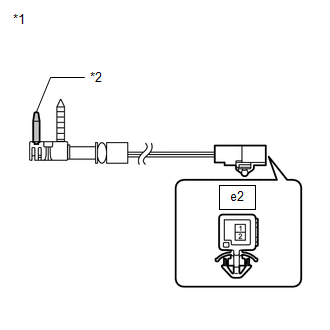
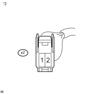
Text in Illustration|
*1 |
Component without harness connected (Evaporator Temperature Sensor) |
|
*2 |
Sensing Portion |
| NG | |
REPLACE EVAPORATOR TEMPERATURE SENSOR |
|
|
3. |
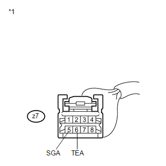
INSPECT AIR CONDITIONING HARNESS (A/C AMPLIFIER - EVAPORATOR TEMPERATURE SENSOR) |
|
(a) Remove the air conditioning harness. |
|
|
(b) Measure the resistance according to the value(s) in the table below. Standard Resistance:
|
|
| OK | |
REPLACE A/C AMPLIFIER |
| NG | |
REPLACE AIR CONDITIONING HARNESS |
 Pressure Sensor Circuit (B1423/23)
DESCRIPTION
This DTC is output when refrigerant pressure on the high pressure side is extremely
low (190 kPa (1.9 kgf/cm2, 28 psi) or less) or extremely high (3140 kPa (32.0 kgf/cm2,
455 psi) or ...
 Compressor Lock Sensor Circuit (B1422/22)
SYSTEM DESCRIPTION
The ECM sends the engine speed signal to the A/C amplifier via CAN communication.
The A/C amplifier reads the difference between compressor speed and engine speed.
When the diff ...
Other materials about Toyota Venza:
Front passenger occupant classification system
Your vehicle is equipped with a front passenger occupant classification system.
This system detects the conditions of the front passenger seat and activates or
deactivates the devices for front passenger.
1. SRS warning light
2. Front passenger’s sea ...
Trailer towing
Your vehicle is designed primarily as a passenger-and-load-carrying vehicle.
Towing a trailer can have an adverse impact on handling, performance, braking, durability,
and fuel consumption. For your safety and the safety of others, you must not overload
...
Problem Symptoms Table
PROBLEM SYMPTOMS TABLE
HINT:
Use the table below to help determine the cause of problem symptoms. If multiple
suspected areas are listed, the potential causes of the symptoms are listed in order
of probability in the "Suspected Area" column of ...

0.1541