Toyota Venza: Back Door Courtesy Switch
Components
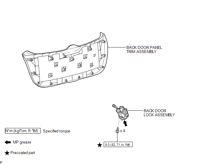
COMPONENTS
ILLUSTRATION
Removal
REMOVAL
PROCEDURE
1. REMOVE BACK DOOR PANEL TRIM ASSEMBLY
.gif)
2. REMOVE BACK DOOR LOCK ASSEMBLY
|
(a) Disconnect the connector. |
|
.png)
(b) Disengage the clamp.
(c) Remove the bolt.
|
(d) Remove the 3 bolts and back door lock assembly. |
|
.png)
Inspection
INSPECTION
PROCEDURE
1. INSPECT BACK DOOR COURTESY SWITCH (BACK DOOR LOCK ASSEMBLY)
(a) Measure the resistance according to the value(s) in the table below.
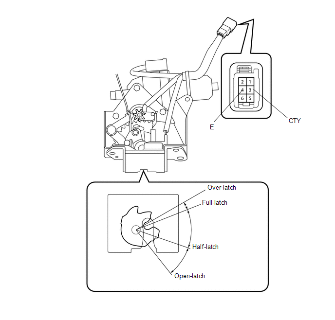
Standard Resistance:
|
Tester Connection |
Condition |
Specified Condition |
|---|---|---|
|
3 (CTY) - 4 (E) |
Open-latched |
Below 1 Ω |
|
3 (CTY) - 4 (E) |
Half-latched |
Below 1 Ω |
|
3 (CTY) - 4 (E) |
Full-latched |
10 kΩ or higher |
|
3 (CTY) - 4 (E) |
Over-latched |
10 kΩ or higher |
If the result is not specified, replace the back door lock assembly.
Installation
INSTALLATION
PROCEDURE
1. INSTALL BACK DOOR LOCK ASSEMBLY
(a) Apply MP grease to the sliding parts of the back door lock assembly.
(b) Apply adhesive to the threads of the bolt.
Adhesive:
Toyota Genuine Adhesive 1324, Three Bond 1324 or equivalent
|
(c) Install the back door lock assembly with the 3 bolts. Torque: 8.0 N·m {82 kgf·cm, 71 in·lbf} |
|
.png)
|
(d) Install the bolt. Torque: 8.0 N·m {82 kgf·cm, 71 in·lbf} |
|
.png)
(e) Engage the clamp.
(f) Connect the connector.
2. INSTALL BACK DOOR PANEL TRIM ASSEMBLY
.gif)
 Lighting (int)
...
 Console Box Light
Components
COMPONENTS
ILLUSTRATION
Removal
REMOVAL
PROCEDURE
1. REMOVE UPPER CONSOLE PANEL SUB-ASSEMBLY (w/o Seat Heater System)
2. REMOVE UPPER CONSOLE PANEL SUB-ASSEMBLY (w/ Seat Hea ...
Other materials about Toyota Venza:
Voice Recognition Microphone Disconnected (B1579)
DESCRIPTION
The navigation receiver assembly and inner rear view mirror assembly (amplifier
microphone assembly) are connected to each other using the microphone connection
detection signal lines.
This DTC is stored when a microphone connection detection ...
System Description
SYSTEM DESCRIPTION
1. GENERAL
(a) To assist the driver with parking the vehicle by displaying an image of the
area behind the vehicle, this system has a rear television camera assembly mounted
on the back door. The system displays the image on the naviga ...
On-vehicle Inspection
ON-VEHICLE INSPECTION
CAUTION / NOTICE / HINT
CAUTION:
Be sure to follow the correct removal and installation procedures of the door
side airbag sensor.
PROCEDURE
1. INSPECT DOOR SIDE AIRBAG SENSOR (VEHICLE NOT INVOLVED IN COLLISION)
(a) Perform a diag ...

0.1225