Toyota Venza: Door Courtesy Light
Components
COMPONENTS
ILLUSTRATION
Removal
REMOVAL
PROCEDURE
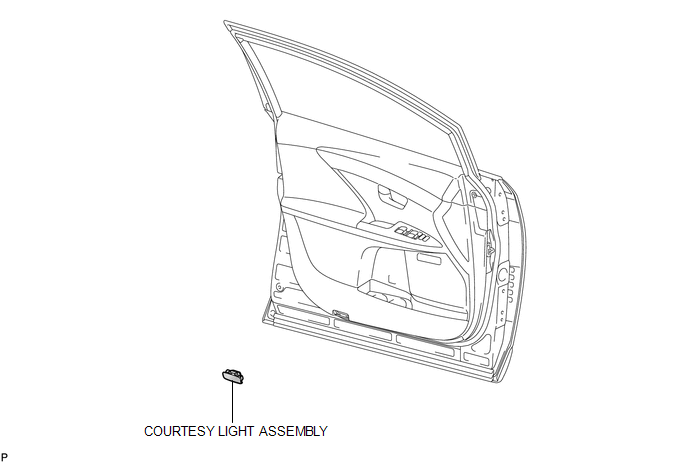
1. REMOVE COURTESY LIGHT ASSEMBLY
|
(a) Using a screwdriver wrapped with protective tape, disengage the claw. Text in Illustration
|
|
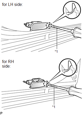
(b) Disconnect the connector and remove the courtesy light assembly.
Inspection
INSPECTION
PROCEDURE
1. INSPECT COURTESY LIGHT ASSEMBLY
|
(a) Connect a positive (+) lead from the battery to terminal 2 and a negative (-) lead to terminal 1. |
|
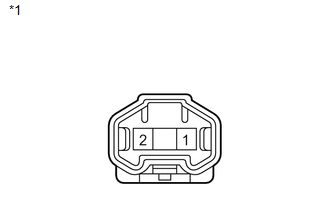
(b) Check that the courtesy light comes on.
OK:
Courtesy light comes on.
Text in Illustration|
*1 |
Component without harness connected (Courtesy Light Assembly) |
If the result is not as specified, replace the bulb or courtesy light assembly.
Installation
INSTALLATION
PROCEDURE
1. INSTALL COURTESY LIGHT ASSEMBLY
(a) Connect the connector.
|
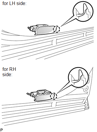
(b) Engage the claw to install the courtesy light assembly. |
|
 Console Box Light
Components
COMPONENTS
ILLUSTRATION
Removal
REMOVAL
PROCEDURE
1. REMOVE UPPER CONSOLE PANEL SUB-ASSEMBLY (w/o Seat Heater System)
2. REMOVE UPPER CONSOLE PANEL SUB-ASSEMBLY (w/ Seat Hea ...
 Front Door Courtesy Switch
Components
COMPONENTS
ILLUSTRATION
Inspection
INSPECTION
PROCEDURE
1. INSPECT COURTESY LIGHT SWITCH
(a) Measure the resistance according to the value(s) in the table below.
Standard Re ...
Other materials about Toyota Venza:
Terminals Of Ecu
TERMINALS OF ECU
1. CHECK POWER BACK DOOR ECU (POWER BACK DOOR MOTOR UNIT) (w/ POWER BACK DOOR
SYSTEM)
(a) Disconnect the L20 power back door ECU connector.
(b) Measure the voltage and resistance according to the value(s) in the table
below.
...
Lost Communication with Clearance Warning ECU (U1110)
DESCRIPTION
DTC Code
DTC Detection Condition
Trouble Area
U1110
No communication from the clearance warning ECU assembly continues.
Clearance warning ECU assembly branch wire o ...
Removal
REMOVAL
CAUTION / NOTICE / HINT
HINT:
Use the same procedure for the LH side and RH side.
The following procedure is for the LH side.
If the sensor rotor needs to be replaced, replace it together with the
front drive shaft assembly.
...

0.1216