Toyota Venza: Components
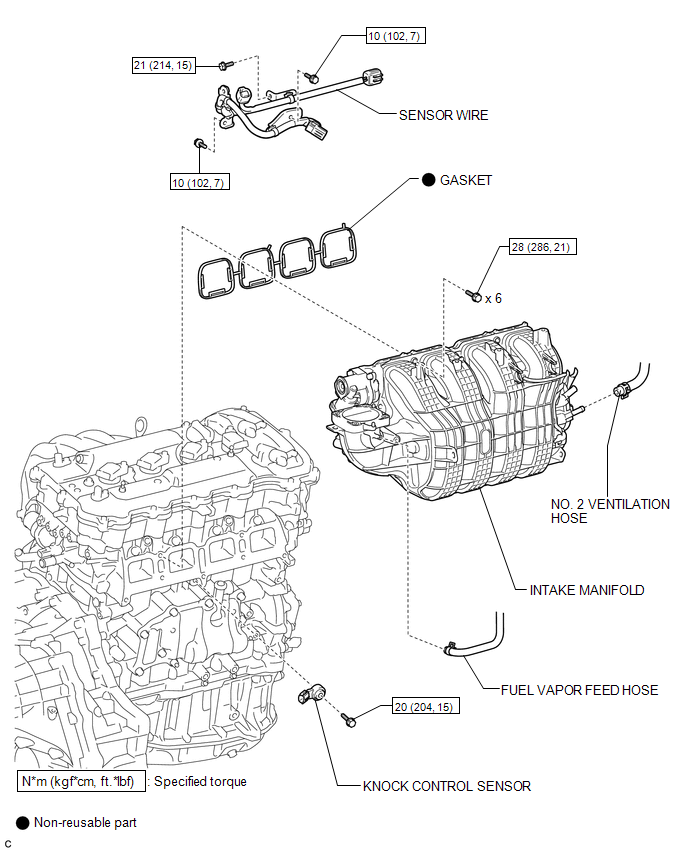
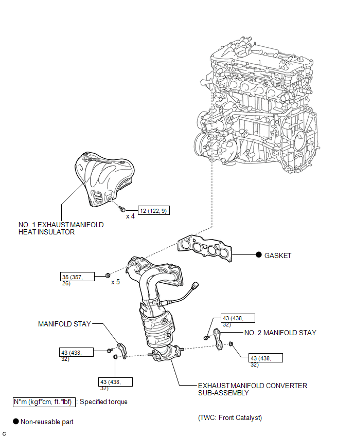
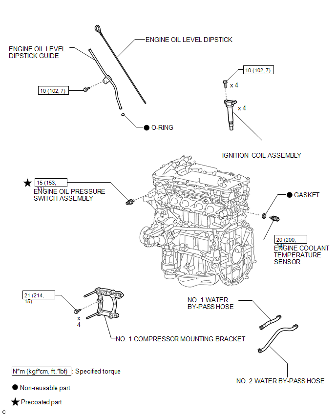
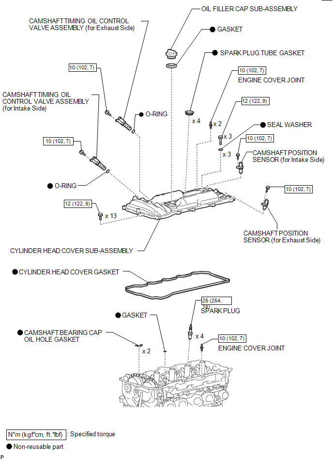
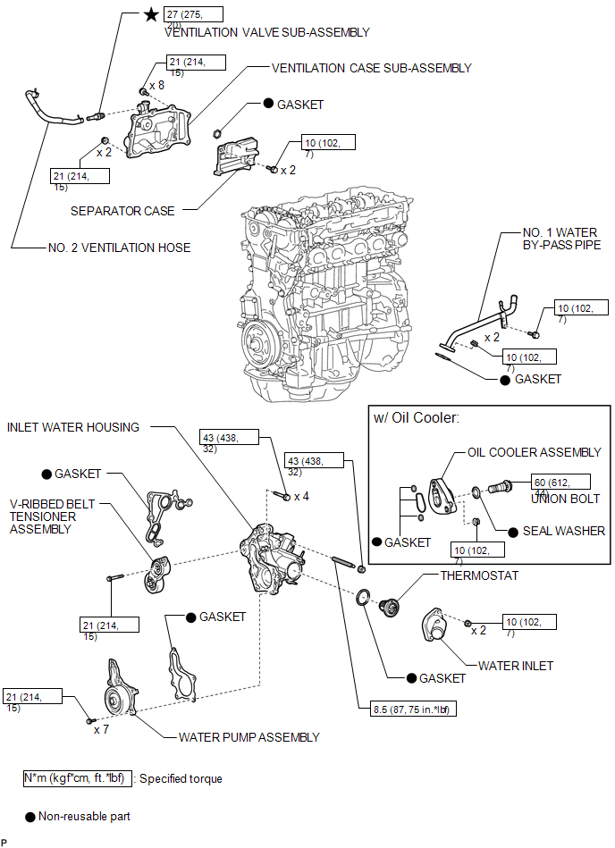
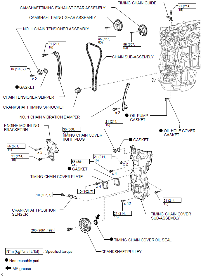
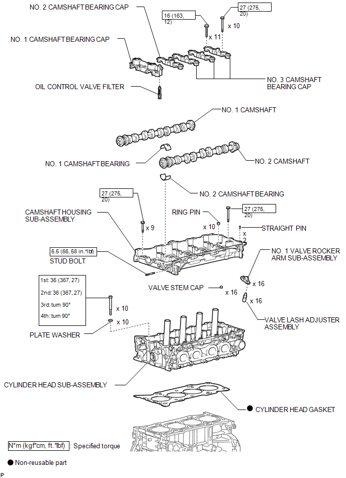
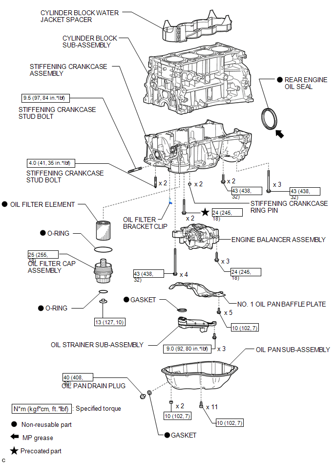
COMPONENTS
ILLUSTRATION
.png)
ILLUSTRATION
.png)
ILLUSTRATION
ILLUSTRATION
ILLUSTRATION
ILLUSTRATION
ILLUSTRATION
ILLUSTRATION
ILLUSTRATION
ILLUSTRATION
 Precaution
PRECAUTION
HINT:
Any digits beyond the 0.01 mm (1/1000 in.) place for standard, minimum
and maximum values should be used as a reference only.
When both standard and maximum or minim ...
 Removal
REMOVAL
PROCEDURE
1. REMOVE ENGINE OIL LEVEL DIPSTICK GUIDE
(a) Remove the engine oil level dipstick.
(b) Remove the bolt and engine oil l ...
Other materials about Toyota Venza:
Illumination Circuit
DESCRIPTION
Power is supplied to the radio and display receiver assembly and steering pad
switch assembly illumination when the light control switch is in the tail or head
position.
WIRING DIAGRAM
CAUTION / NOTICE / HINT
NOTICE:
The vehicle ...
Entry Answer-back Buzzer does not Sound
DESCRIPTION
The smart key system uses the wireless door lock buzzer to perform various vehicle
exterior warnings. When the conditions for each warning are met, the certification
ECU (smart key ECU assembly) sends a buzzer request signal to the main body E ...
Portable Player cannot be Connected Manually/Automatically
CAUTION / NOTICE / HINT
HINT:
Some versions of "Bluetooth" compatible audio players may not function properly,
or the functions may be limited using the navigation receiver assembly, even if
the portable audio player itself can play files (See ...

0.1262