Toyota Venza: Components
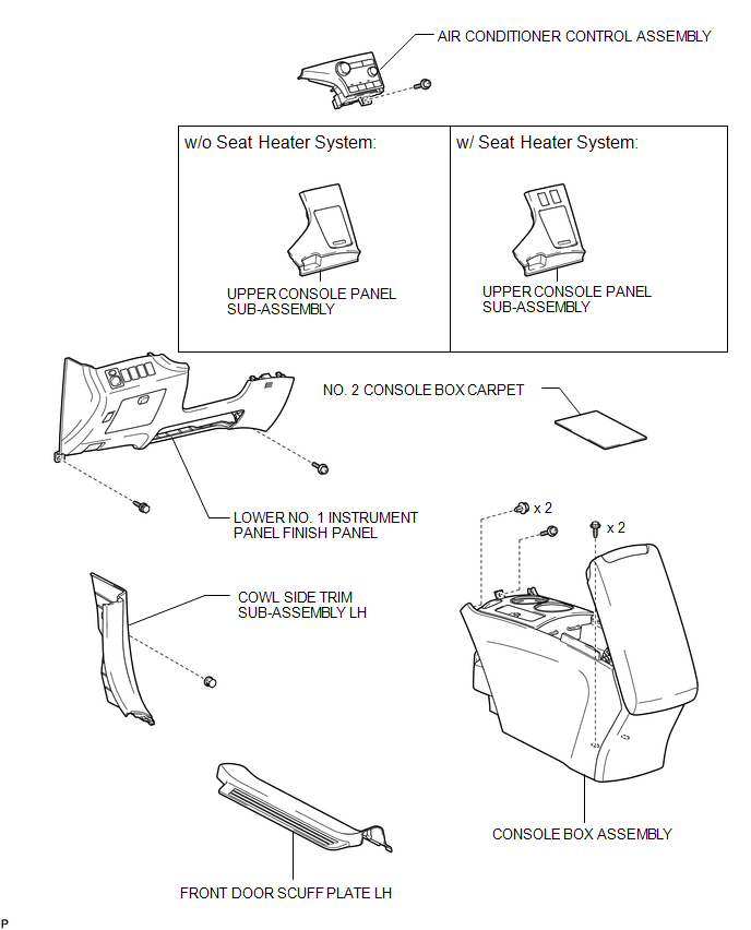
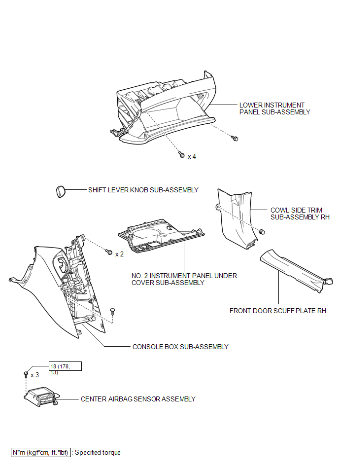
COMPONENTS
ILLUSTRATION
ILLUSTRATION

 On-vehicle Inspection
ON-VEHICLE INSPECTION
PROCEDURE
1. INSPECT CENTER AIRBAG SENSOR ASSEMBLY (VEHICLE NOT INVOLVED IN COLLISION)
(a) Perform a diagnostic system check (See page
).
2. INSPECT CENTER AIRBAG SENSOR AS ...
Other materials about Toyota Venza:
Lubrication system
- Engine oil selection
“Toyota Genuine Motor Oil” is used in your Toyota vehicle. Use Toyota approved
“Toyota Genuine Motor Oil” or equivalent to satisfy the following grade and viscosity.
Oil grade: ILSAC GF-5 multigrade engine oil
Recomm ...
Cooling System
On-vehicle Inspection
ON-VEHICLE INSPECTION
PROCEDURE
1. INSPECT FOR COOLANT LEAK
CAUTION:
Do not remove the radiator cap while the engine and radiator are still hot. Pressurized
hot engine coolant and steam may be released and cause serious burns.
N ...
Diagnostic Trouble Code Chart
DIAGNOSTIC TROUBLE CODE CHART
HINT:
If a trouble code is stored during the DTC check, inspect the trouble areas listed
for that code. For details of the code, refer to "See page" below.
1. TRANSPONDER KEY ECU DIAGNOSTIC TROUBLE CODE CHART
Trans ...

0.1276