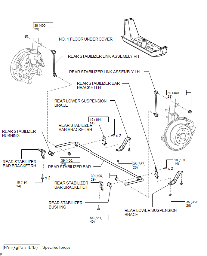
Toyota Venza: Components
COMPONENTS
ILLUSTRATION

 Inspection
INSPECTION
PROCEDURE
1. INSPECT REAR STABILIZER LINK ASSEMBLY
(a) Move the ball joint stud back and forth 5 times before installing
the nut as shown in the illustration.
...
Other materials about Toyota Venza:
Vehicle Speed Signal Circuit between Stereo Component Amplifier and Combination
Meter
DESCRIPTION
The stereo component amplifier assembly receives a vehicle speed signal from
the combination meter assembly to control the ASL function.
HINT:
A voltage of 12 V or 5 V is output from each ECU and then input to the
combination meter ...
Installation
INSTALLATION
PROCEDURE
1. INSTALL FRONT DOOR BELT MOULDING
(a) Engage the 5 claws to install the front door belt moulding.
(b) Install the clip.
2. INSTALL FRONT DOOR GLASS RUN
3. INSTALL FRONT ...
Transfer Case Rear Oil Seal
Components
COMPONENTS
ILLUSTRATION
ILLUSTRATION
Replacement
REPLACEMENT
PROCEDURE
1. REMOVE TAIL EXHAUST PIPE ASSEMBLY
2. REMOVE CENTER EXHAUST PIPE ASSEMBLY
3. REMOVE PROPELLER WITH CENTER BEARING SHAFT ASSEMBLY
4. REMOVE TRANSFER C ...

0.1731