Toyota Venza: Components
COMPONENTS
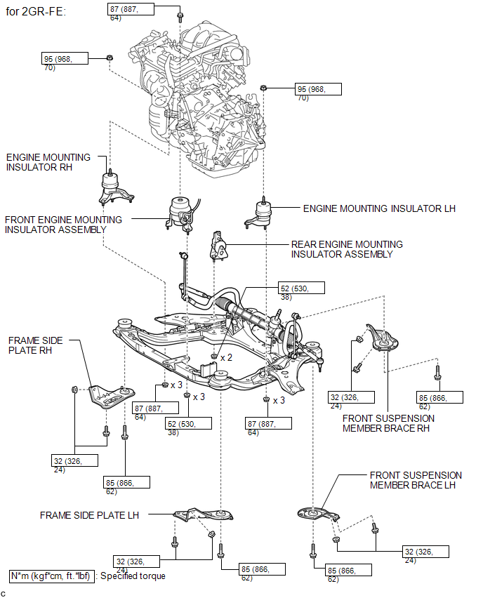
ILLUSTRATION
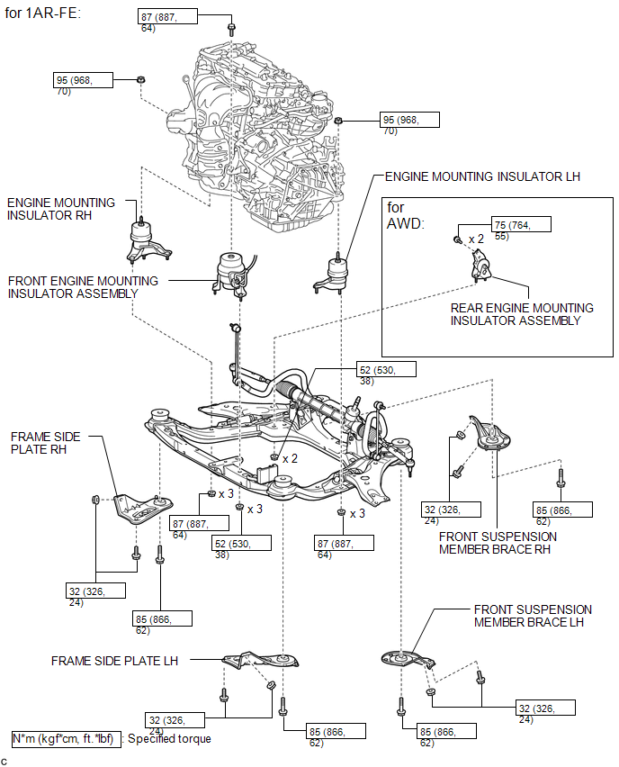
ILLUSTRATION
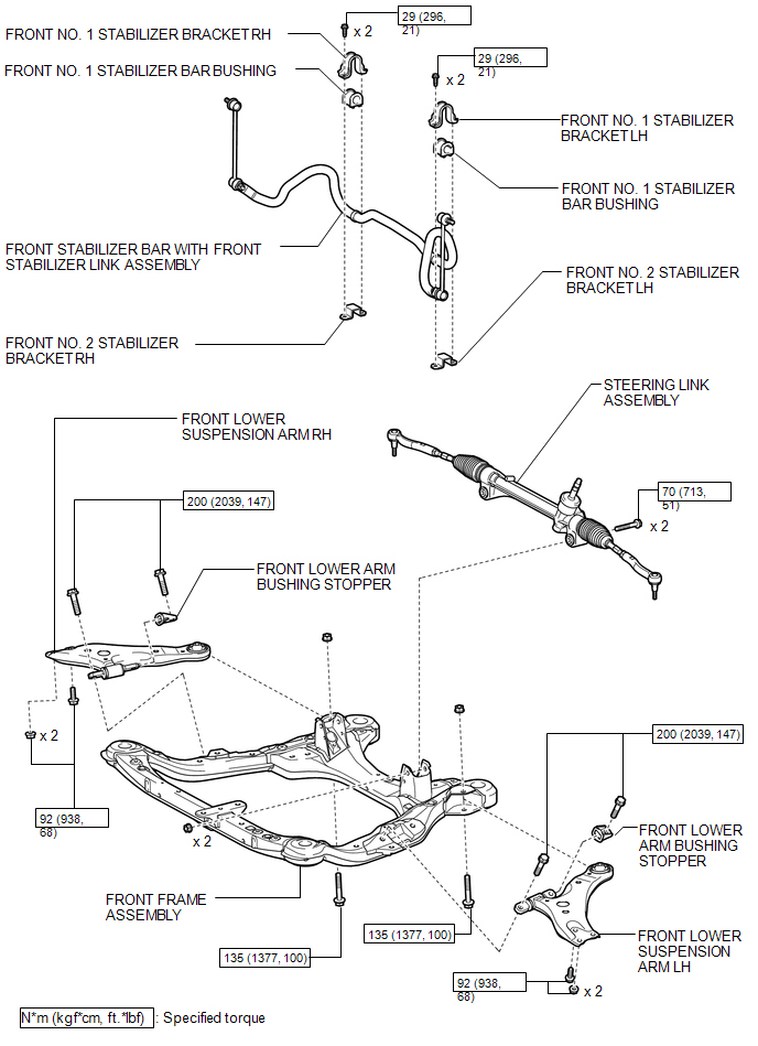
ILLUSTRATION
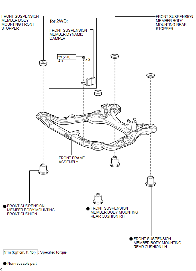
ILLUSTRATION

 Removal
REMOVAL
PROCEDURE
1. REMOVE ENGINE ASSEMBLY WITH TRANSAXLE (for 2GR-FE)
HINT:
Refer to the procedure up to Remove Engine Assembly with Transaxle (See page
).
2. REMOVE ENGINE ASSEMBLY WITH TRAN ...
Other materials about Toyota Venza:
Installation
INSTALLATION
PROCEDURE
1. INSTALL CENTER AIRBAG SENSOR ASSEMBLY
(a) Check that the ignition switch is off.
(b) Check that the cable is disconnected from the negative (-) battery terminal.
CAUTION:
Wait at least 90 seconds after disconnecting the cable fr ...
Removal
REMOVAL
PROCEDURE
1. REMOVE NO. 1 FLOOR UNDER COVER
(a) Disengage the 4 nuts and clip, and remove the No. 1 floor under cover.
Text in Illustration
Nut (attached to under cover)
HINT:
Rotate the clip to disengage it. The 4 ...
Air Outlet Damper Control Servo Motor Circuit (B1443/43)
DESCRIPTION
The air outlet control servo motor sends pulse signals to indicate the damper
position to the A/C amplifier. The A/C amplifier activates the motor (normal or
reverse) based on these signals to move the mode damper to any position, which contro ...

0.139