Toyota Venza: Amplifier Antenna
Components
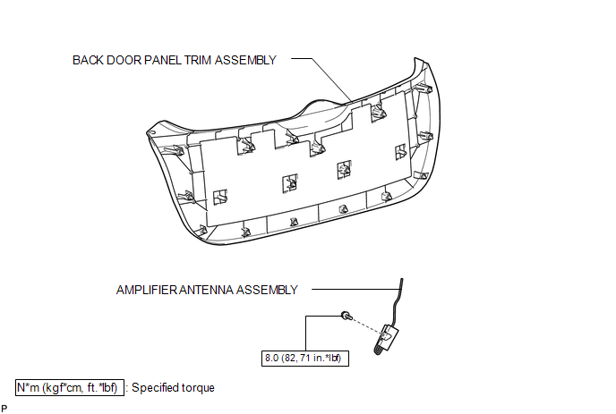
COMPONENTS
ILLUSTRATION
Removal
REMOVAL
PROCEDURE
1. REMOVE BACK DOOR PANEL TRIM ASSEMBLY
.gif)
2. REMOVE AMPLIFIER ANTENNA ASSEMBLY
|
(a) Disconnect the 2 connectors. |
|
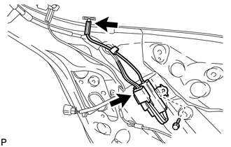
(b) Remove the bolt and amplifier antenna assembly.
Installation
INSTALLATION
PROCEDURE
1. INSTALL AMPLIFIER ANTENNA ASSEMBLY
|
(a) Install the amplifier antenna assembly with the bolt. Torque: 8.0 N·m {82 kgf·cm, 71 in·lbf} |
|
.png)
(b) Connect the 2 connectors.
2. INSTALL BACK DOOR PANEL TRIM ASSEMBLY
.gif)
 Audio / Video
...

Other materials about Toyota Venza:
Reassembly
REASSEMBLY
PROCEDURE
1. INSTALL NO. 2 STEERING RACK BOOT
(a) Apply lithium soap base glycol grease to the inside of the small
opening of a new No. 2 steering rack boot.
(b) Install the No. 2 ste ...
Transfer Case Front Oil Seal(for Rh Side)
Components
COMPONENTS
ILLUSTRATION
Replacement
REPLACEMENT
PROCEDURE
1. DRAIN TRANSFER OIL
(a) Remove the transfer drain plug and gasket to drain the transfer oil.
(b) Install a new gasket and the transfer drain plug.
Torque:
49 N·m {500 kgf ...
Installation
INSTALLATION
PROCEDURE
1. INSTALL MANUAL VALVE
(a) Coat the manual valve with ATF and install it to the transmission valve body
assembly.
2. SUPPORT ENGINE ASSEMBLY
3. INSTALL TRANSMISSION VALVE BODY ASSEMBLY
(a) Coat the O-ring of the transmission ...

0.1334