Toyota Venza: Clock Display Circuit
DESCRIPTION
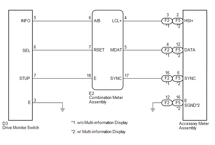
The accessory meter assembly uses this circuit to communicate with the combination meter assembly via the direct line. The accessory meter assembly uses this circuit to receive the drive monitor switch signals from the combination meter assembly via the direct line and multi-information display signal from each ECU through the combination meter assembly via the direct line.
HINT:
Each ECU outputs the DTCs when each system has a malfunction.
WIRING DIAGRAM
PROCEDURE
|
1. |
SYSTEM CHECK |
(a) Confirm the symptom.
|
Result |
Proceed to |
|---|---|
|
Clock display does not indicate cruise information display (The display only illuminates). |
A |
|
Multi-information display does not change when the drive monitor switch is operated. |
B |
| B | .gif) |
GO TO STEP 5 |
|
.gif)
|
2. |
CHECK CAN COMMUNICATION SYSTEM |
(a) Check if a CAN communication DTC is output (See page
.gif) ).
).
|
Result |
Proceed to |
|---|---|
|
CAN communication DTC is not output. |
A |
|
CAN communication DTC is output. |
B |
| B | |
GO TO CAN COMMUNICATION SYSTEM |
|
|
3. |
CHECK HARNESS AND CONNECTOR (ACCESSORY METER ASSEMBLY - COMBINATION METER ASSEMBLY) |
(a) Disconnect the E2 and F2*1 or F5*2 connectors.
(b) Measure the resistance according to the value(s) in the table below.
Standard Resistance:
|
Tester Connection |
Condition |
Specified Condition |
|---|---|---|
|
F2-3 (HSI+)*1 - E2-4 (LCL+) |
Always |
Below 1 Ω |
|
F2-4 (DATA)*1 - E2-5 (MDAT) |
Always |
Below 1 Ω |
|
F2-16 (SYNC)*1 - E2-17 (SYNC) |
Always |
Below 1 Ω |
|
F5-2 (HSI+)*2 - E2-4 (LCL+) |
Always |
Below 1 Ω |
|
F5-12 (DATA)*2 - E2-5 (MDAT) |
Always |
Below 1 Ω |
|
F5-6 (SYNC)*2 - E2-17 (SYNC) |
Always |
Below 1 Ω |
|
E2-4 (LCL+) - Body ground |
Always |
10 kΩ or higher |
|
E2-5 (MDAT) - Body ground |
Always |
10 kΩ or higher |
|
E2-17 (SYNC) - Body ground |
Always |
10 kΩ or higher |
|
F5-16 (SGND)*2 - Body ground |
Always |
Below 1 Ω |
|
F2-12 (E) - Body ground |
Always |
Below 1 Ω |
- *1: w/o Multi-information Display
- *2: w/ Multi-information Display
| NG | |
REPAIR OR REPLACE HARNESS OR CONNECTOR |
|
|
4. |
INSPECT COMBINATION METER ASSEMBLY |
|
(a) Reconnect the E2 connector. |
|
(b) Measure the voltage according to the value(s) in the table below.
Standard Voltage:
|
Tester Connection |
Condition |
Specified Condition |
|---|---|---|
|
F2-3 (HSI+)*1 - Body ground |
Ignition switch ON |
Pulse generation |
|
F2-4 (DATA)*1 - Body ground |
Ignition switch ON |
Pulse generation |
|
F2-16 (SYNC)*1 - Body ground |
Ignition switch ON |
Pulse generation |
|
F5-2 (HSI+)*2 - Body ground |
Ignition switch ON |
Pulse generation |
|
F5-12 (DATA)*2 - Body ground |
Ignition switch ON |
Pulse generation |
|
F5-6 (SYNC)*2 - Body ground |
Ignition switch ON |
Pulse generation |
- *1: w/o Multi-information Display
- *2: w/ Multi-information Display
|
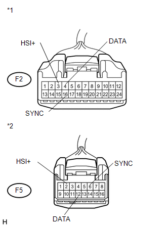
*1 |
Front view of wire harness connector (to Accessory Meter Assembly (w/o Multi-information Display)) |
|
*2 |
Front view of wire harness connector (to Accessory Meter Assembly (w/ Multi-information Display)) |
| OK | |
REPLACE ACCESSORY METER ASSEMBLY |
| NG | |
REPLACE COMBINATION METER ASSEMBLY |
|
5. |
CHECK HARNESS AND CONNECTOR (COMBINATION METER ASSEMBLY - DRIVE MONITOR SWITCH) |
(a) Disconnect the E2 and D3 connectors.
(b) Measure the resistance according to the value(s) in the table below.
Standard Resistance:
|
Tester Connection |
Condition |
Specified Condition |
|---|---|---|
|
E2-6 (A/B) - D3-5 (INFO) |
Always |
Below 1 Ω |
|
E2-6 (A/B)- Body ground |
Always |
10 kΩ or higher |
|
E2-7 (RSET) - D3-6 (SEL) |
Always |
Below 1 Ω |
|
E2-7 (RSET) - Body ground |
Always |
10 kΩ or higher |
|
E2-18 (E) - D3-7 (STUP) |
Always |
Below 1 Ω |
|
E2-18 (E)- Body ground |
Always |
10 kΩ or higher |
|
D3-3 (E) - Body ground |
Always |
Below 1 Ω |
| NG | |
REPAIR OR REPLACE HARNESS OR CONNECTOR |
|
|
6. |
INSPECT DRIVE MONITOR SWITCH |
|
(a) Disconnect the D3 connector. |
|
(b) Measure the resistance according to the value(s) in the table below.
Standard Resistance:
|
Tester Connection |
Condition |
Specified Condition |
|---|---|---|
|
3 (E) - 5 (INFO) |
Ignition switch ON and INFO CLOCK*1 or INFO*2 switch pressed |
Below 1 Ω |
|
Ignition switch ON and INFO CLOCK*1 or INFO*2 switch released |
10 kΩ or higher |
|
|
3 (E) - 6 (SEL) |
Ignition switch ON and RESET H*1 or SELECT RESET*2 switch pressed |
Below 1 Ω |
|
Ignition switch ON and RESET H*1 or SELECT RESET*2 switch released |
10 kΩ or higher |
|
|
3 (E) - 7 (STUP) |
Ignition switch ON and US/M M*1 or SETUP*2 switch pressed |
Below 1 Ω |
|
Ignition switch ON and US/M M*1 or SETUP*2 switch released |
10 kΩ or higher |
- *1: w/o Multi-information Display
- *2: w/ Multi-information Display
|
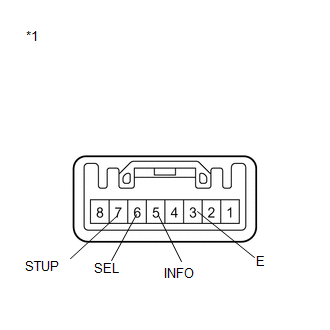
*1 |
Component without harness connected (Drive Monitor Switch) |
| OK | |
REPLACE COMBINATION METER ASSEMBLY |
| NG | |
REPLACE DRIVE MONITOR SWITCH |
 Meter Illumination is Always Dark
DESCRIPTION
In this circuit, the meter CPU receives auto dimmer signals from the main body
ECU (driver side junction block assembly) using the CAN communication system (CAN
No. 1 Bus). When the m ...
 Speed Signal Circuit
DESCRIPTION
The combination meter assembly receives the vehicle speed signal from this circuit.
The wheel speed sensors produce an output that varies according to the vehicle speed.
The wheel spe ...
Other materials about Toyota Venza:
Removal
REMOVAL
PROCEDURE
1. PRECAUTION
CAUTION:
Be sure to read Precaution thoroughly before servicing (See page
).
2. DISCONNECT CABLE FROM NEGATIVE BATTERY TERMINAL
CAUTION:
Wait at least 90 seconds after disconnecting the cable from the negative (-)
bat ...
Precaution
PRECAUTION
1. PRECAUTION FOR DISCONNECTING CABLE FROM NEGATIVE BATTERY TERMINAL
NOTICE:
When disconnecting the cable from the negative (-) battery terminal, initialize
the following system after the cable is reconnected.
System Name
...
Removal
REMOVAL
CAUTION / NOTICE / HINT
HINT:
Use the same procedure for the RH and LH sides.
The procedure described below is for the LH side.
PROCEDURE
1. PRECAUTION (for HID Headlight)
(See page )
NOTICE:
After turning the ignition switch ...

0.1249