Toyota Venza: Speed Signal Circuit
DESCRIPTION
The combination meter assembly receives the vehicle speed signal from this circuit. The wheel speed sensors produce an output that varies according to the vehicle speed. The wheel speed sensor output is received by the skid control ECU which uses this information to create the vehicle speed sensor signal*1. The vehicle speed sensor signal consists of pulses sent to the combination meter assembly from the skid control ECU. To create this signal, 12 V is output from IG2 which is behind a resistor in the combination meter assembly. This voltage is sent to the skid control ECU. The pulse signal is created by switching the transistor in the skid control ECU on and off, making the voltage on the wire drop to 0 V. A similar system is used for the output of this signal from the combination meter assembly via terminal +S. A voltage of 12 V or 5 V is applied to terminal +S from each ECU or relay that is connected to this terminal. The transistor in the combination meter assembly is controlled by the signal from the skid control ECU. When this transistor is turned on, this transistor makes the voltage supplied by the various ECUs (via their respective internal resistors) drop to 0 V. Each ECU connected to terminal +S of the combination meter assembly controls its respective system based on the pulse signal.
- *1: This vehicle speed sensor signal is created by the skid control ECU. There is no actual component that is referred to as the vehicle speed sensor. In addition, for some other systems, vehicle speed information may be exchanged using CAN communication.
HINT:
This circuit is used for the systems connected to terminal +S. This signal is not used for combination meter assembly operation. Combination meter assembly components such as the speedometer operate using data received via CAN communication.
WIRING DIAGRAM
1. for 2GR-FE
.png)
2. for 1AR-FE
.png)
PROCEDURE
|
1. |
INSPECT ECU TERMINAL VOLTAGE (INPUT VOLTAGE) |
|
(a) Disconnect the E1 connector. |
|
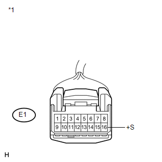
(b) Measure the voltage according to the value(s) in the table below.
Standard Voltage:
|
Tester Connection |
Condition |
Specified Condition |
|---|---|---|
|
E1-16 (+S) - Body ground |
Ignition switch ON |
4.5 to 14 V |
|
*1 |
Front view of wire harness connector (to Combination Meter Assembly) |
HINT:
If any of the ECUs specified in the wiring diagram supplies power to the combination meter assembly, the combination meter assembly will output a waveform.
| NG | .gif) |
GO TO STEP 5 |
|
.gif)
|
2. |
INSPECT COMBINATION METER ASSEMBLY (OUTPUT VOLTAGE) |
(a) Reconnect the E1 connector.
|
(b) Disconnect the A42 connector. |
|
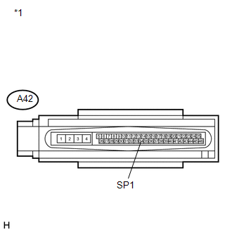
(c) Measure the voltage according to the value(s) in the table below.
Standard Voltage:
|
Tester Connection |
Condition |
Specified Condition |
|---|---|---|
|
A42-33 (SP1) - Body ground |
Ignition switch ON |
11 to 14 V |
|
*1 |
Front view of wire harness connector (to Skid Control ECU) |
| NG | |
GO TO STEP 4 |
|
|
3. |
INSPECT SKID CONTROL ECU (INPUT WAVEFORM) |
|
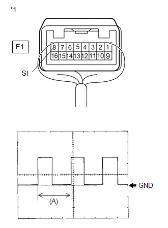
(a) Check the input waveform. (1) Reconnect the A42 connector. (2) Remove the combination meter assembly with the connector(s) still connected. (3) Connect an oscilloscope to terminal E1-8 (SI) and body ground. (4) Turn the ignition switch ON. (5) Turn the wheel slowly. (6) Check the signal waveform according to the condition(s) in the table below.
OK: The waveform is displayed as shown in the illustration. HINT: When the system is functioning normally, one wheel revolution generates 4 pulses. As the vehicle speed increases, the width indicated by (A) in the illustration narrows. |
|
| OK | |
REPLACE COMBINATION METER ASSEMBLY |
| NG | |
REPLACE SKID CONTROL ECU |
|
4. |
CHECK HARNESS AND CONNECTOR (COMBINATION METER ASSEMBLY - SKID CONTROL ECU) |
(a) Disconnect the E1 and A42 connectors.
(b) Measure the resistance according to the value(s) in the table below.
Standard Resistance:
|
Tester Connection |
Condition |
Specified Condition |
|---|---|---|
|
A42-33 (SP1) - E1-8 (SI) |
Always |
Below 1 Ω |
|
A42-33 (SP1) - Body ground |
Always |
10 kΩ or higher |
| OK | |
REPLACE COMBINATION METER ASSEMBLY |
| NG | |
REPAIR OR REPLACE HARNESS OR CONNECTOR |
|
5. |
CHECK HARNESS AND CONNECTOR (COMBINATION METER ASSEMBLY - JUNCTION CONNECTOR) |
(a) Disconnect the E31 junction connector.
(b) Measure the resistance according to the value(s) in the table below.
Standard Resistance:
|
Tester Connection |
Condition |
Specified Condition |
|---|---|---|
|
E1-16 (+S) - E31-19 |
Always |
Below 1 Ω |
|
E1-16 (+S) - Body ground |
Always |
10 kΩ or higher |
| NG | |
REPAIR OR REPLACE HARNESS OR CONNECTOR |
|
|
6. |
CHECK JUNCTION CONNECTOR |
(a) Check for a short in the circuit that is connected to the junction connector shown in the wiring diagram.
HINT:
If voltage is not present, it is possible that an ECU or circuit has a malfunction. The malfunctioning ECU or circuit will be diagnosed in the following steps.
|
(1) Disconnect the D57 junction connector. |
|
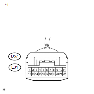
(2) Measure the voltage according to the value(s) in the table below.
Standard Voltage:
|
Tester Connection |
Condition |
Specified Condition |
|---|---|---|
|
E31-20 - Body ground |
Ignition switch ON |
4.5 to 14 V |
|
E31-21 - Body ground |
Ignition switch ON |
4.5 to 14 V |
|
D57-13 - Body ground |
Ignition switch ON |
4.5 to 14 V |
|
D57-14 - Body ground |
Ignition switch ON |
4.5 to 14 V |
|
D57-15 - Body ground |
Ignition switch ON |
4.5 to 14 V |
|
*1 |
Front view of wire harness connector (to Junction Connector) |
|
Result |
Proceed to |
|---|---|
|
Voltage is not present in one circuit. |
A |
|
Voltage is present in all the circuits. |
B |
| B | |
REPLACE JUNCTION CONNECTOR |
|
|
7. |
CHECK HARNESS AND CONNECTOR (JUNCTION CONNECTOR - JUNCTION CONNECTOR) |
(a) Disconnect the D55 junction connector.
(b) Measure the resistance according to the value(s) in the table below.
Standard Resistance:
|
Tester Connection |
Condition |
Specified Condition |
|---|---|---|
|
D57-14 - D55-17 |
Always |
Below 1 Ω |
|
D57-14 - Body ground |
Always |
10 kΩ or higher |
| NG | |
REPAIR OR REPLACE HARNESS OR CONNECTOR |
|
|
8. |
CHECK JUNCTION CONNECTOR |
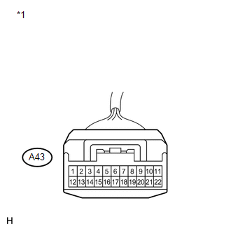
(a) Check for a short in the circuit that is connected to A43 junction connector shown in the wiring diagram.
HINT:
If voltage is not present, it is possible that an ECU or circuit has a malfunction. The malfunctioning ECU or circuit will be diagnosed in the following steps.
|
(1) Disconnect the A43 junction connector. |
|
(2) Measure the voltage according to the value(s) in the table below.
Standard Voltage:
|
Tester Connection |
Condition |
Specified Condition |
|---|---|---|
|
A43-16 - Body ground |
Ignition switch ON |
4.5 to 14 V |
|
A43-17 - Body ground |
Ignition switch ON |
4.5 to 14 V |
|
A43-18 - Body ground |
Ignition switch ON |
4.5 to 14 V |
|
*1 |
Front view of wire harness connector (to Junction Connector) |
|
Result |
Proceed to |
|---|---|
|
Voltage is not present in one circuit. |
A |
|
Voltage is present in all the circuits. |
B |
| B | |
REPLACE JUNCTION CONNECTOR |
|
|
9. |
SYSTEM CHECK |
(a) Select the circuit in which voltage is not present in step 6.
|
Tester Connection |
System that Uses the Circuit |
Proceed to |
|---|---|---|
|
D57-15 - Body ground |
Tire Pressure Warning System |
A |
|
D57-13 - Body ground |
Smart Key System*1 |
B |
|
E31-21 - Body ground |
Audio and Visual System*2 |
C |
|
E31-20 - Body ground |
Audio and Visual System or Navigation System |
D |
|
D57-14 - Body ground |
SFI System, Automatic Transaxle System or Lighting System*3 |
E |
- *1: w/ Smart Key System
- *2: for 13 Speakers
- *3: w/ Automatic Type Headlight Beam Level Control
| B | |
GO TO STEP 11 |
| C | |
GO TO STEP 12 |
| D | |
GO TO STEP 13 |
| E | |
GO TO STEP 14 |
|
|
10. |
CHECK HARNESS AND CONNECTOR (TIRE PRESSURE WARNING ECU CIRCUIT) |
(a) Disconnect the D31 connector.
(b) Measure the resistance according to the value(s) in the table below.
Standard Resistance:
|
Tester Connection |
Condition |
Specified Condition |
|---|---|---|
|
D31-2 (SPD) - Body ground |
Always |
10 kΩ or higher |
| OK | |
REPLACE TIRE PRESSURE WARNING ECU |
| NG | |
REPAIR OR REPLACE HARNESS OR CONNECTOR |
|
11. |
CHECK HARNESS AND CONNECTOR (POWER MANAGEMENT CONTROL ECU CIRCUIT) |
(a) Disconnect the D43 connector.
(b) Measure the resistance according to the value(s) in the table below.
Standard Resistance:
|
Tester Connection |
Condition |
Specified Condition |
|---|---|---|
|
D43-23 (SUT) - Body ground |
Always |
10 kΩ or higher |
| OK | |
REPLACE POWER MANAGEMENT CONTROL ECU |
| NG | |
REPAIR OR REPLACE HARNESS OR CONNECTOR |
|
12. |
CHECK HARNESS AND CONNECTOR (STEREO COMPONENT AMPLIFIER CIRCUIT) |
(a) Disconnect the E14 connector.
(b) Measure the resistance according to the value(s) in the table below.
Standard Resistance:
|
Tester Connection |
Condition |
Specified Condition |
|---|---|---|
|
E14-11 (SPD) - Body ground |
Always |
10 kΩ or higher |
| OK | |
REPLACE STEREO COMPONENT AMPLIFIER |
| NG | |
REPAIR OR REPLACE HARNESS OR CONNECTOR |
|
13. |
CHECK HARNESS AND CONNECTOR (RADIO AND DISPLAY RECEIVER ASSEMBLY CIRCUIT, NAVIGATION RECEIVER ASSEMBLY CIRCUIT) |
(a) Disconnect the E42*1 or E40*2 connector.
(b) Measure the resistance according to the value(s) in the table below.
Standard Resistance:
|
Tester Connection |
Condition |
Specified Condition |
|---|---|---|
|
E42-17 (SPD)*1 - Body ground |
Always |
10 kΩ or higher |
|
E40-17 (SPD)*2- Body ground |
Always |
10 kΩ or higher |
- *1: w/o Navigation System
- *2: w/ Navigation System
|
Result |
Proceed to |
|---|---|
|
OK (w/o Navigation System) |
A |
|
OK (w/ Navigation System) |
B |
|
NG |
C |
| A | |
REPLACE RADIO AND DISPLAY RECEIVER ASSEMBLY |
| B | |
REPLACE NAVIGATION RECEIVER ASSEMBLY |
| C | |
REPAIR OR REPLACE HARNESS OR CONNECTOR |
|
14. |
SYSTEM CHECK |
(a) Select the circuit in which is not present voltage in step 8.
|
Tester Connection |
System that Uses the Circuit |
Proceed to |
|---|---|---|
|
A43-17 - Body ground |
SFI System |
A |
|
A43-16 - Body ground |
Automatic Transaxle System |
B |
|
A43-18 - Body ground |
Lighting System*1 |
C |
- *1: w/ Automatic Type Headlight Beam Level Control
| B | |
GO TO STEP 16 |
| C | |
GO TO STEP 17 |
|
|
15. |
CHECK HARNESS AND CONNECTOR (ECM CIRCUIT) |
(a) Disconnect the A41*1 or A49*2 connector.
(b) Measure the resistance according to the value(s) in the table below.
Standard Resistance:
|
Tester Connection |
Condition |
Specified Condition |
|---|---|---|
|
A41-13 (SPD)*1 - Body ground |
Always |
10 kΩ or higher |
|
A49-15 (SPD)*2 - Body ground |
Always |
10 kΩ or higher |
- *1: for 2GR-FE
- *2: for 1AR-FE
|
Result |
Proceed to |
|---|---|
|
OK (for 2GR-FE) |
A |
|
OK (for 1AR-FE) |
B |
|
NG |
C |
| A | |
REPLACE ECM (for 2GR-FE) |
| B | |
REPLACE ECM (for 1AR-FE) |
| C | |
REPAIR OR REPLACE HARNESS OR CONNECTOR |
|
16. |
CHECK HARNESS AND CONNECTOR (TCM CIRCUIT) |
(a) Disconnect the B40 connector.
(b) Measure the resistance according to the value(s) in the table below.
Standard Resistance:
|
Tester Connection |
Condition |
Specified Condition |
|---|---|---|
|
B40-3 (SPD) - Body ground |
Always |
10 kΩ or higher |
|
Result |
Proceed to |
|---|---|
|
OK (for U660E Automatic Transaxle System) |
A |
|
OK (for U660F Automatic Transaxle System) |
B |
|
OK (for U760E Automatic Transaxle System) |
C |
|
OK (for U760F Automatic Transaxle System) |
D |
|
NG |
E |
| A | |
REPLACE TCM (for U660E) |
| B | |
REPLACE TCM (for U660F) |
| C | |
REPLACE TCM (for U760E) |
| D | |
REPLACE TCM (for U760F) |
| E | |
REPAIR OR REPLACE HARNESS OR CONNECTOR |
|
17. |
CHECK HARNESS AND CONNECTOR (HEADLIGHT LEVELING ECU ASSEMBLY CIRCUIT) |
(a) Disconnect the A40 connector.
(b) Measure the resistance according to the value(s) in the table below.
Standard Resistance:
|
Tester Connection |
Condition |
Specified Condition |
|---|---|---|
|
A40-16 (SPDR) - Body ground |
Always |
10 kΩ or higher |
| OK | |
REPLACE HEADLIGHT LEVELING ECU ASSEMBLY |
| NG | |
REPAIR OR REPLACE HARNESS OR CONNECTOR |
 Clock Display Circuit
DESCRIPTION
The accessory meter assembly uses this circuit to communicate with the combination
meter assembly via the direct line. The accessory meter assembly uses this circuit
to receive the dr ...
 Power Source Circuit
DESCRIPTION
1. w/o Multi-information Display
(a) This circuit is the power source circuit for the accessory meter assembly.
This circuit provides two types of power sources; one is a constant powe ...
Other materials about Toyota Venza:
Installation
INSTALLATION
PROCEDURE
1. INSTALL REAR SEAT ASSEMBLY RH
(a) Place the rear seat assembly RH in the cabin.
NOTICE:
Be careful not to damage the vehicle body.
(b) Temporarily install the 2 bolts on the front side of the seat.
...
Screen Flicker or Color Distortion
PROCEDURE
1.
CHECK DISPLAY SETTING
(a) Reset display settings (contrast, brightness) and check that the screen appears
normal.
OK:
The display returns to normal.
OK
END
NG
...
Slide Sensor Malfunction (B2650)
DESCRIPTION
When the position control ECU and switch assembly does not receive a sensor signal
despite forward or backward movement of seat by power seat motor operation, this
DTC is output.
DTC Code
DTC Detection Condition
...

0.1532