Toyota Venza: Camshaft Position "A" - Timing Over-Advanced or System Performance (Bank 1) (P0011,P0012)
DESCRIPTION
Refer to DTC P0010 (See page .gif) ).
).
|
DTC No. |
DTC Detection Condition |
Trouble Area |
|---|---|---|
|
P0011 |
The valve timing is stuck at a certain value when in the advance range (1 trip detection logic). |
|
|
P0012 |
The valve timing is stuck at a certain value when in the retard range (2 trip detection logic). |
MONITOR DESCRIPTION
- The ECM optimizes the intake valve timing using the Variable Valve Timing (VVT) system to control the intake camshaft. The VVT system includes the ECM, the camshaft timing oil control valve assembly and the VVT controller (camshaft timing gear assembly). The ECM sends a target duty-cycle control signal to the camshaft timing oil control valve assembly. This control signal regulates the oil pressure supplied to the VVT controller. The VVT controller can advance or retard the intake camshaft.
- If the difference between the target and actual intake valve timing is large, and changes in the actual intake valve timing are small, the ECM interprets this as the VVT controller stuck malfunction and stores a DTC.
- Example:
- A DTC is set when the following conditions "A" and "B" are met:
- It takes 5 seconds or more to change the valve timing by 5°CA (Condition "A").
- After the above condition is met, the camshaft timing oil control valve assembly is forcibly activated for 10 seconds (Condition "B").
- DTC P0011 (Advanced Cam Timing) is subject to 1 trip detection logic.
- DTC P0012 (Retarded Cam Timing) is subject to 2 trip detection logic.
- These DTCs indicate that the VVT controller cannot operate properly due to camshaft timing oil control valve assembly malfunctions or the presence of foreign objects in the camshaft timing oil control valve assembly.
MONITOR STRATEGY
|
Related DTCs |
P0011: Advanced Camshaft Timing P0012: Retarded Camshaft Timing |
|
Required Sensors/Components (Main) |
Camshaft timing oil control valve assembly and VVT controller |
|
Required Sensors/Components (Related) |
Crankshaft position sensor Camshaft position sensor Engine coolant temperature sensor |
|
Frequency of Operation |
Continuous |
|
Duration |
Within 10 seconds |
|
MIL Operation |
Advanced camshaft timing: Immediate Retarded camshaft timing: 2 driving cycles |
|
Sequence of Operation |
None |
TYPICAL ENABLING CONDITIONS
|
Monitor runs whenever following DTCs not stored |
P0010 (Camshaft Timing Oil Control Valve) P0016 (VVT System - Misalignment) P0102, P0103 (Mass Air Flow Meter) P0115, P0117, P0118 (Engine Coolant Temperature Sensor) P0125 (Insufficient Coolant Temperature for Closed Loop Fuel Control) P0335 (Crankshaft Position Sensor) P0340 (Camshaft Position Sensor) |
|
Battery voltage |
11 V or higher |
|
Engine speed |
400 to 4000 rpm |
|
Engine coolant temperature |
75 to 100°C (167 to 212°F) |
TYPICAL MALFUNCTION THRESHOLDS
P0011: Advanced Camshaft Timing|
Both of following conditions are met |
- |
|
Deviation of actual valve timing and target valve timing |
More than 5°CA (Crankshaft Angle) for 5 seconds or more after the VVT hold duty ratio learned value reaches the upper or lower limit. |
|
Valve timing |
No change at advanced valve timing |
|
Both of following conditions are met |
- |
|
Deviation of actual valve timing and target valve timing |
More than 5°CA (Crankshaft Angle) for 5 seconds or more after the VVT hold duty ratio learned value reaches the upper or lower limit. |
|
Valve timing |
No change at retarded valve timing |
- If the difference between the target and actual camshaft timing is greater than the specified value, the ECM operates the camshaft timing oil control valve assembly for 10 seconds by applying and releasing oil pressure. Then, the ECM monitors the camshaft timing change for 10 seconds.
MONITOR RESULT
Refer to Checking Monitor Status (See page
).
CONFIRMATION DRIVING PATTERN
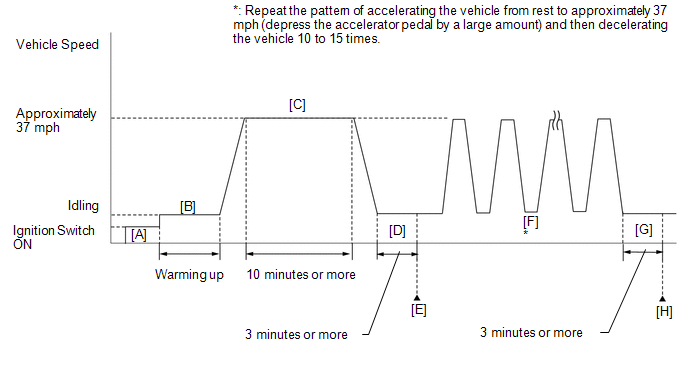
- Connect the Techstream to the DLC3.
- Turn the ignition switch to ON and turn the Techstream on.
- Clear the DTCs (even if no DTCs are stored, perform the clear DTC operation)
(See page ).
- Turn the ignition switch off and wait for at least 30 seconds.
- Turn the ignition switch to ON and turn the Techstream on [A].
- Start the engine and warm it up until the engine coolant temperature reaches 75°C (167°F) or higher [B].
- Drive the vehicle at approximately 60 km/h (37 mph) for 10 minutes or
more [C].
CAUTION:
When performing the confirmation driving pattern, obey all speed limits and traffic laws.
- Idle the engine for 3 minutes or more [D].
- Enter the following menus: Powertrain / Engine / Trouble Codes [E].
- Read the pending DTCs.
HINT:
- If a pending DTC is output, the system is malfunctioning.
- If a pending DTC is not output, perform the following procedure.
- Enter the following menus: Powertrain / Engine / Utility / All Readiness.
- Input the DTC: P0011, P0012.
- Check the DTC judgment result.
Techstream Display
Description
NORMAL
- DTC judgment completed
- System normal
ABNORMAL
- DTC judgment completed
- System abnormal
INCOMPLETE
- DTC judgment not completed
- Perform driving pattern after confirming DTC enabling conditions
N/A
- Unable to perform DTC judgment
- Number of DTCs which do not fulfill DTC preconditions has reached ECU memory limit
HINT:
- If the judgment result shows NORMAL, the system is normal.
- If the judgment result shows ABNORMAL, the system has a malfunction.
- If the judgment result shows INCOMPLETE or N/A, perform steps [F] through [H].
- Repeat the pattern of accelerating the vehicle from rest to approximately
60 km/h (37 mph) and then decelerating the vehicle 10 to 15 times [F].
CAUTION:
When performing the confirmation driving pattern, obey all speed limits and traffic laws.
HINT:
Depress the accelerator pedal by a large amount.
- Idle the engine for 3 minutes or more [G].
- Enter the following menus: Powertrain / Engine / Trouble Codes [H].
- Read the pending DTCs.
HINT:
- If a pending DTC is output, the system is malfunctioning.
- If a pending DTC is not output, perform the following procedure.
- Check the DTC judgment result again.
HINT:
- If the judgment result shows NORMAL, the system is normal.
- If the judgment result shows ABNORMAL, the system has a malfunction.
- If the judgment result shows INCOMPLETE or N/A, perform the following procedure.
- Perform a universal trip and check for permanent DTCs (See page
).
HINT:
- If a permanent DTC is output, the system is malfunctioning.
- If no permanent DTC is output, the system is normal.
WIRING DIAGRAM
Refer to DTC P0010 (See page ).
CAUTION / NOTICE / HINT
HINT:
- DTC P0011 or P0012 may be stored when foreign objects in the engine oil are caught in some parts of the system. The DTC will remain set even if the system returns to normal after a short time. Those foreign objects may then be captured by the oil filter.
- Read freeze frame data using the Techstream. The ECM records vehicle and driving condition information as freeze frame data the moment a DTC is stored. When troubleshooting, freeze frame data can help determine if the vehicle was moving or stationary, if the engine was warmed up or not, if the air fuel ratio was lean or rich, and other data from the time the malfunction occurred.
PROCEDURE
|
1. |
CHECK ANY OTHER DTCS OUTPUT (IN ADDITION TO DTC P0011 OR P0012) |
(a) Connect the Techstream to the DLC3.
(b) Turn the ignition switch to ON.
(c) Turn the Techstream on.
(d) Enter the following menus: Powertrain / Engine / Trouble Codes.
(e) Read the DTCs.
|
Result |
Proceed to |
|---|---|
|
DTC P0011 or P0012 is output |
A |
|
DTC P0011 or P0012 and other DTCs are output |
B |
HINT:
If any DTCs other than P0011 or P0012 are output, troubleshoot those DTCs first.
| B | .gif) |
GO TO DTC CHART |
|
.gif)
|
2. |
PERFORM ACTIVE TEST USING TECHSTREAM (OPERATE CAMSHAFT TIMING OIL CONTROL VALVE ASSEMBLY) |
(a) Connect the Techstream to the DLC3.
(b) Start the engine.
(c) Turn the Techstream on.
(d) Turn the A/C switch on.
(e) Enter the following menus: Powertrain / Engine / Active Test / Control the VVT Linear (Bank 1).
(f) Check the engine speed while operating the camshaft timing oil control valve assembly (for intake camshaft) using the Techstream.
OK:
|
Techstream Operation |
Specified Condition |
|---|---|
|
0% |
Normal engine speed |
|
100% |
Engine idles roughly or stalls |
HINT:
If the result is not acceptable, cool the engine (engine coolant temperature is 50°C (122°F) or less) and perform the Active Test again.
| NG | |
GO TO STEP 4 |
|
|
3. |
CHECK WHETHER DTC OUTPUT RECURS (DTC P0011 OR P0012) |
(a) Connect the Techstream to the DLC3.
(b) Turn the ignition switch to ON.
(c) Turn the Techstream on.
(d) Clear the DTCs (See page ).
(e) Turn the ignition switch off and wait for at least 30 seconds.
(f) Turn the ignition switch to ON and turn the Techstream on.
(g) Start the engine.
(h) Drive the vehicle in accordance with the driving pattern described in the Confirmation Driving Pattern.
(i) Enter the following menus: Powertrain / Engine / Trouble Codes / Pending.
(j) Read the pending DTCs.
|
Result |
Proceed to |
|---|---|
|
DTC is not output |
A |
|
DTC P0011 or P0012 is output |
B |
HINT:
DTC P0011 or P0012 may be stored when foreign objects in the engine oil are caught in some parts of the system. The DTC will remain stored even if the system returns to normal after a short time. These foreign objects may then be captured by the oil filter.
| A | |
CHECK FOR INTERMITTENT PROBLEMS |
|
|
4. |
INSPECT CAMSHAFT TIMING OIL CONTROL VALVE ASSEMBLY (FOR INTAKE CAMSHAFT) |
(a) Inspect the camshaft timing oil control valve assembly (for intake camshaft)
(See page ).
| NG | |
REPLACE CAMSHAFT TIMING OIL CONTROL VALVE ASSEMBLY |
|
|
5. |
CHECK VALVE TIMING |
(a) Remove the cylinder head cover (See page
).
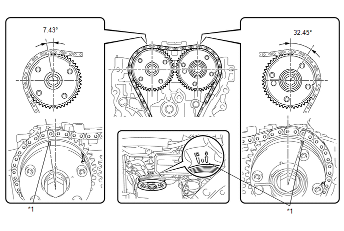 Text in Illustration
|
*1 |
Timing Mark |
- |
- |
(b) Turn the crankshaft pulley, and align its groove with the timing mark "0" of the timing chain cover.
(c) Check that the timing marks of the camshaft timing gears are aligned with the timing marks as shown in the illustration.
HINT:
If the timing marks are not as shown, turn the crankshaft one revolution clockwise.
OK:
Timing marks on camshaft timing gears are aligned as shown in the illustration.
| NG | |
GO TO STEP 9 |
|
|
6. |
INSPECT OIL CONTROL VALVE FILTER |
|
(a) Remove the oil control valve filter (See page
|
|
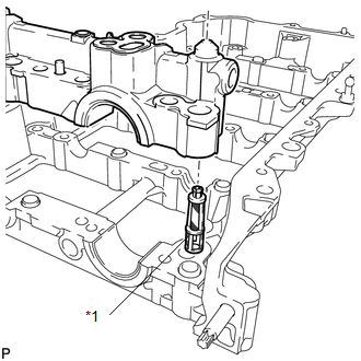
(b) Check that the filter is not clogged.
OK:
Filter is not clogged.
Text in Illustration|
*1 |
Oil Control Valve Filter |
| NG | |
REPLACE OIL CONTROL VALVE FILTER |
|
|
7. |
REPLACE CAMSHAFT TIMING GEAR ASSEMBLY |
(a) Replace the camshaft timing gear assembly (See page
).
HINT:
Perform "Inspection After Repair" after replacing the camshaft timing gear assembly
(See page ).
|
|
8. |
CHECK WHETHER DTC OUTPUT RECURS (DTC P0011 OR P0012) |
(a) Connect the Techstream to the DLC3.
(b) Turn the ignition switch to ON.
(c) Turn the Techstream on.
(d) Clear the DTCs (See page ).
(e) Turn the ignition switch off and wait for at least 30 seconds.
(f) Turn the ignition switch to ON and turn the Techstream on.
(g) Start the engine.
(h) Drive the vehicle in accordance with the driving pattern described in the Confirmation Driving Pattern.
(i) Enter the following menus: Powertrain / Engine / Trouble Codes / Pending.
(j) Read the pending DTCs.
|
Result |
Proceed to |
|---|---|
|
DTC is not output |
A |
|
DTC P0011 or P0012 is output |
B |
| A | |
END |
| B | |
REPLACE ECM |
|
9. |
CHECK ENGINE MECHANICAL SYSTEM |
(a) Check for mechanical malfunctions that affect the valve timing, such as a jumped tooth or stretching of the timing chain.
| NG | |
REPAIR OR REPLACE MALFUNCTIONING PARTS, COMPONENT AND AREA |
|
|
10. |
CHECK WHETHER DTC OUTPUT RECURS |
(a) Connect the Techstream to the DLC3.
(b) Turn the ignition switch to ON.
(c) Turn the Techstream on.
(d) Clear the DTCs (See page ).
(e) Turn the ignition switch off and wait for at least 30 seconds.
(f) Turn the ignition switch to ON and turn the Techstream on.
(g) Start the engine.
(h) Drive the vehicle in accordance with the driving pattern described in the Confirmation Driving Pattern.
(i) Enter the following menus: Powertrain / Engine / Trouble Codes / Pending.
(j) Read the pending DTCs.
|
Result |
Proceed to |
|---|---|
|
DTC is not output |
A |
|
DTC P0011 or P0012 is output |
B |
| A | |
CHECK FOR INTERMITTENT PROBLEMS |
| B | |
REPLACE ECM |
 Camshaft Position "A" Actuator Circuit (Bank 1) (P0010)
DESCRIPTION
The Variable Valve Timing (VVT) system adjusts the intake valve timing to improve
driveability. The engine oil pressure turns the VVT controller to adjust the valve
timing.
The camsh ...
 Camshaft Position "B" Actuator Circuit / Open (Bank 1) (P0013)
DESCRIPTION
The Variable Valve Timing (VVT) system adjusts the exhaust valve timing to improve
driveability. The engine oil pressure turns the VVT controller to adjust the valve
timing.
The cams ...
Other materials about Toyota Venza:
Installation
INSTALLATION
PROCEDURE
1. INSTALL TRANSMISSION CONTROL CABLE ASSEMBLY
NOTICE:
Before installing the transmission control cable assembly, check that the park/neutral
position switch and the shift lever are in neutral.
(a) Pass the control cable from the ...
Removal
REMOVAL
PROCEDURE
1. REMOVE REAR DOOR SCUFF PLATE
2. DISCONNECT REAR DOOR OPENING TRIM WEATHERSTRIP
3. REMOVE TONNEAU COVER ASSEMBLY (w/ Tonneau Cover)
4. REMOVE DECK BOARD ASSEMBLY
5. REMOVE NO. 3 DECK BOARD SUB-ASSEMBLY
6. REMOVE DECK S ...
Brake Switch "A" / "B" Correlation (P0504)
DESCRIPTION
The stop light switch is a duplex system that transmits 2 signals: STP and ST1-.
These 2 signals are used by the ECM to monitor whether or not the brake system is
working properly. If signals which indicate the brake pedal is being depressed a ...

1.0347