Toyota Venza: Removal
REMOVAL
PROCEDURE
1. REMOVE REAR DOOR SCUFF PLATE
.gif)
2. DISCONNECT REAR DOOR OPENING TRIM WEATHERSTRIP
3. REMOVE TONNEAU COVER ASSEMBLY (w/ Tonneau Cover)
4. REMOVE DECK BOARD ASSEMBLY
5. REMOVE NO. 3 DECK BOARD SUB-ASSEMBLY
6. REMOVE DECK SIDE TRIM BOX LH
7. REMOVE NO. 2 DECK BOARD SUB-ASSEMBLY
8. REMOVE DECK SIDE TRIM BOX RH
9. REMOVE NO. 1 DECK BOARD
10. REMOVE REAR SEAT SUB FLOOR PANEL ASSEMBLY
11. REMOVE REAR FLOOR FINISH PLATE
12. REMOVE REAR SEAT HEADREST ASSEMBLY (for LH Side)
13. REMOVE REAR SEAT INNER TRACK BRACKET COVER (for LH Side)
14. REMOVE REAR SEAT OUTER TRACK BRACKET COVER (for LH Side)
15. DISCONNECT REAR SEAT NO. 2 RECLINING CONTROL CABLE SUB-ASSEMBLY (for LH Side)
16. REMOVE REAR SEAT ASSEMBLY LH (for LH Side)
17. REMOVE REAR SEAT HEADREST ASSEMBLY (for RH Side)
18. REMOVE REAR SEAT CENTER HEADREST ASSEMBLY (for RH Side)
19. REMOVE REAR SEAT INNER TRACK BRACKET COVER (for RH Side)
20. REMOVE REAR SEAT OUTER TRACK BRACKET COVER (for RH Side)
21. DISCONNECT REAR SEAT RECLINING CONTROL CABLE SUB-ASSEMBLY (for RH Side)
22. REMOVE REAR SEAT ASSEMBLY RH (for RH Side)
23. REMOVE RECLINING REMOTE CONTROL BEZEL
24. REMOVE LUGGAGE HOLD BELT STRIKER ASSEMBLY
25. DISCONNECT REAR SEAT OUTER BELT ASSEMBLY
26. REMOVE DECK TRIM SIDE PANEL ASSEMBLY LH (for LH Side)
27. REMOVE DECK TRIM SIDE PANEL ASSEMBLY RH (for RH Side)
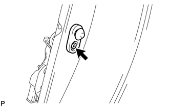
28. REMOVE REAR DOOR COURTESY LIGHT SWITCH
(a) Disconnect the rear door courtesy light switch connector.
|
(b) Using "TORX" socket wrench T30, remove the "TORX" bolt and rear door courtesy light switch. |
|
 Components
COMPONENTS
ILLUSTRATION
ILLUSTRATION
ILLUSTRATION
ILLUSTRATION
ILLUSTRATION
...
 Inspection
INSPECTION
PROCEDURE
1. INSPECT COURTESY LIGHT SWITCH
(a) Measure the resistance according to the value(s) in the table below.
Standard Resistance:
Tester Connection
Swit ...
Other materials about Toyota Venza:
Inspection
INSPECTION
PROCEDURE
1. INSPECT INTEGRATION RELAY
(a) Inner circuit (for 2GR-FE)
(1) for EFI MAIN relay
Measure the resistance according to the value(s) in the table
below.
Standard Resistance:
...
Operation Check
OPERATION CHECK
1. NOTICE WHEN CHECKING THE FOLLOWING
(a) Power door lock/unlock function:
This wireless door lock control function operates only when the following 3 conditions
are met:
(1) There is no key in the ignition key cylinder.
(2) All doors ar ...
Short in Torque Converter Clutch Solenoid Circuit (Shift Solenoid Valve SL)
(P2769,P2770)
DESCRIPTION
Shift solenoid valve SL is turned on and off by signals from the TCM to control
the hydraulic pressure acting on the lock-up relay valve, which then controls operation
of the lock-up clutch.
DTC No.
DTC Detection Conditi ...

0.1701