Toyota Venza: Brake Pedal Load Sensing Switch (C1267/67)
DESCRIPTION
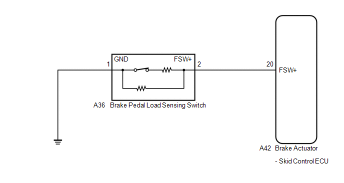
The brake pedal load sensing switch is turned on when the brake pedal is depressed with force exceeding a predetermined level.
The skid control ECU detects if the brake pedal is depressed or not via this circuit.
|
DTC Code |
DTC Detection Condition |
Trouble Area |
|---|---|---|
|
C1267/67 |
Any of the following is detected:
|
|
WIRING DIAGRAM
CAUTION / NOTICE / HINT
HINT:
When C1249/49 is output together with C1267/67, inspect and repair the trouble
areas indicated by C1249/49 first (See page .gif) ).
).
PROCEDURE
|
1. |
READ VALUE USING TECHSTREAM (STOP LIGHT SWITCH AND BRAKE PEDAL LOAD SENSING SWITCH) |
(a) Connect the Techstream to the DLC3.
(b) Turn the ignition switch to ON.
(c) Select the Data List on the Techstream (See page
).
ABS/VSC/TRAC
|
Tester Display |
Measurement Item/Range |
Normal Condition |
Diagnostic Note |
|---|---|---|---|
|
Stop Light SW |
Stop light switch / ON or OFF |
ON: Brake pedal depressed OFF: Brake pedal released |
- |
|
Brake Pedal Load Sensing SW |
Brake pedal load sensing switch / ON or OFF |
ON: Brake pedal depressed beyond the specified point OFF: Brake pedal not depressed beyond the specified point |
- |
(d) Check that the stop light switch display and brake pedal load sensing switch display observed on the Techstream change according to brake pedal operation.
OK:
The Techstream displays ON or OFF according to brake pedal operation.
(e) Slowly depress the brake pedal, and check when the stop light switch and brake pedal load sensing switch turn on.
OK:
First the stop light switch should turn on, and then the brake pedal load sensing switch should turn on.
|
Result |
Proceed to |
|---|---|
|
OK |
A |
|
NG (The brake pedal load sensing switch does not turn on) |
B |
|
NG (The brake pedal load sensing switch turns on first) |
C |
| B | .gif) |
GO TO STEP 3 |
| C | |
GO TO STEP 5 |
|
.gif)
|
2. |
RECONFIRM DTC |
(a) Turn the ignition switch off.
(b) Clear the DTCs (See page ).
(c) Start the engine.
(d) Perform a road test.
(e) Check if the same DTC is recorded (See page
).
|
Result |
Proceed to |
|---|---|
|
DTC (C1267/67) is not output |
A |
|
DTC (C1267/67) is output |
B |
| A | |
CHECK FOR INTERMITTENT PROBLEMS |
| B | |
REPLACE BRAKE ACTUATOR ASSEMBLY |
|
3. |
INSPECT BRAKE PEDAL LOAD SENSING SWITCH |
.png)
NOTICE:
- Do not remove the brake pedal load sensing switch from the brake pedal support assembly.
- When there is a malfunction in the brake pedal load sensing switch, replace the brake pedal support assembly.
(a) Turn the ignition switch off.
(b) Make sure that there is no looseness at the locking part and the connecting part of the connector.
(c) Disconnect the brake pedal load sensing switch connector.
(d) Measure the resistance according to the value(s) in the table below.
Standard Resistance:
|
Tester Connection |
Switch Condition |
Specified Condition |
|---|---|---|
|
2 (FSW+) - 1 (GND) |
Brake pedal load sensing switch off (Brake pedal depressed) |
950 to 1050 Ω |
|
2 (FSW+) - 1 (GND) |
Brake pedal load sensing switch on (Brake pedal released) |
203 to 223 Ω |
| NG | |
REPLACE BRAKE PEDAL SUPPORT ASSEMBLY (BRAKE PEDAL LOAD SENSING SWITCH) |
|
|
4. |
CHECK HARNESS AND CONNECTOR (SKID CONTROL ECU - BRAKE PEDAL LOAD SENSING SWITCH) |
(a) Make sure that there is no looseness at the locking part and the connecting part of the connector.
(b) Disconnect the skid control ECU connector.
(c) Measure the resistance according to the value(s) in the table below.
Standard Resistance:
|
Tester Connection |
Condition |
Specified Condition |
|---|---|---|
|
A42-20 (FSW+) - A36-2 (FSW+) |
Always |
Below 1 Ω |
|
A42-20 (FSW+) - Body ground |
Always |
10 kΩ or higher |
|
A36-1 (GND) - Body ground |
Always |
Below 1 Ω |
|
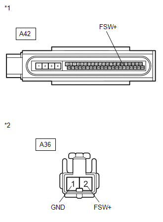
*1 |
Front view of wire harness connector (to Brake Actuator (Skid Control ECU)) |
|
*2 |
Front view of wire harness connector (to Brake Pedal Support Assembly (Brake Pedal Load Sensing Switch)) |
| OK | |
REPLACE BRAKE ACTUATOR ASSEMBLY |
| NG | |
REPAIR OR REPLACE HARNESS OR CONNECTOR |
|
5. |
CHECK BRAKE PEDAL AND STOP LIGHT SWITCH INSTALLATION |
(a) Turn the ignition switch off.
(b) Check the brake pedal height and stop light switch installation (See page
).
OK:
The brake pedal height and stop light switch installation are normal.
| OK | |
REPLACE BRAKE PEDAL SUPPORT ASSEMBLY (BRAKE PEDAL LOAD SENSING SWITCH) |
| NG | |
ADJUST BRAKE PEDAL OR STOP LIGHT SWITCH |
 Skid Control ECU Malfunction (C1300/62)
DESCRIPTION
The skid control ECU outputs this DTC, if malfunctions are found in the circuit
inside the ECU by self diagnosis.
DTC Code
DTC Detection Condition
Trou ...
 ECU Version Miss Match (C1288/88)
DESCRIPTION
DTC Code
DTC Detection Condition
Trouble Area
C1288/88
ECM does not match.
ECM
PROCEDURE
1.
...
Other materials about Toyota Venza:
Power Back Door cannot be Operated Using Any Switch
DESCRIPTION
When the power back door cannot be operated using any switch, one of the following
may be the cause: 1) initialization of the power back door ECU (power back door
motor unit), 2) power back door touch sensor circuit, 3) power back door main sw ...
Installation
INSTALLATION
PROCEDURE
1. INSTALL COOLER CONDENSER ASSEMBLY
(a) Install the cooler condenser assembly with the 4 bolts.
Torque:
6.0 N·m {61 kgf·cm, 53 in·lbf}
HINT:
If the condenser is replaced with a new one, add compressor oil t ...
Removal
REMOVAL
CAUTION / NOTICE / HINT
NOTICE:
Do not replace the spiral cable with the battery connected and the ignition
switch ON.
Do not rotate the spiral cable without the steering wheel with the battery
connected and the ignition switch O ...

0.1204