Toyota Venza: Tire Pressure Warning Light Circuit
DESCRIPTION
If the tire pressure warning ECU detects a malfunction, the tire pressure warning light blinks for 1 minute then stays on and tire pressure monitor is canceled at the same time. At this time, the ECU records a DTC in the memory.
Connecting terminals TC and CG of the DLC3 allows the tire pressure warning light to blink output DTCs.
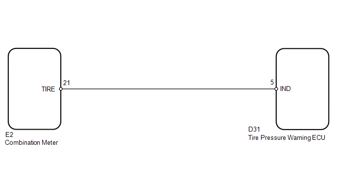
WIRING DIAGRAM
CAUTION / NOTICE / HINT
NOTICE:
- When replacing the tire pressure warning ECU, read the transmitter IDs stored in the old ECU using the Techstream and write them down before removal.
- It is necessary to perform registration (See page
.gif) ) of the transmitter IDs into the tire
) of the transmitter IDs into the tire
pressure warning ECU if the ECU has been replaced.
PROCEDURE
|
1. |
CHECK OPERATION OF TIRE PRESSURE WARNING LIGHT (ACTIVE TEST) |
(a) Turn the ignition switch off.
(b) Connect the Techstream to the DLC3.
(c) Turn the ignition switch to ON.
(d) Turn the Techstream on.
(e) Enter the following menus: Body Electrical / Combination Meter / Active Test.
(f) Check the condition of the tire pressure warning light by operating the Techstream.
Combination Meter|
Tester Display |
Test Part |
Control Range |
Diagnostic Note |
|---|---|---|---|
|
Indicat. Tire Pressure Warning System |
Tire pressure warning light |
Tire pressure warning light is off or on |
Confirm that the vehicle is stopped with the engine idling |
OK:
The warning light turns on when operating the Techstream.
| NG | .gif) |
GO TO METER / GAUGE SYSTEM |
|
.gif)
|
2. |
CHECK HARNESS AND CONNECTOR (COMBINATION METER - TIRE PRESSURE WARNING ECU) |
|
(a) Disconnect the E2 combination meter connector. |
|
(b) Disconnect the D31 tire pressure warning ECU connector.
(c) Measure the resistance according to the value(s) in the table below.
Standard Resistance:
|
Tester Connection |
Condition |
Specified Condition |
|---|---|---|
|
E2-21 (TIRE) - D31-5 (IND) |
Always |
Below 1 Ω |
|
E2-21 (TIRE) - Body ground |
10 kΩ or higher |
|
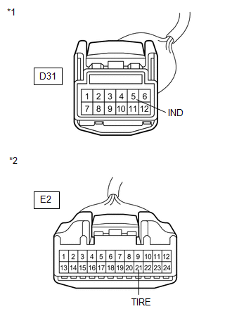
*1 |
Front view of wire harness connector (to Tire Pressure Warning ECU) |
|
*2 |
Front view of wire harness connector (to Combination Meter) |
| OK | |
REPLACE TIRE PRESSURE WARNING ECU |
| NG | |
REPAIR OR REPLACE HARNESS OR CONNECTOR |
 ECU Power Source Circuit
DESCRIPTION
This is the power source for the tire pressure warning ECU.
WIRING DIAGRAM
CAUTION / NOTICE / HINT
NOTICE:
When replacing the tire pressure warning ECU, read the transmitter ...
 TC and CG Terminal Circuit
DESCRIPTION
DTC output mode is set by connecting terminals 13 (TC) and 4 (CG) of the DLC3.
The DTCs are indicated by the blinking pattern of the tire pressure warning light.
WIRING DIAGRAM
HINT ...
Other materials about Toyota Venza:
Components
COMPONENTS
ILLUSTRATION
ILLUSTRATION
ILLUSTRATION
ILLUSTRATION
ILLUSTRATION
ILLUSTRATION
ILLUSTRATION
...
Occupant Classification ECU Malfunction (B1795)
DESCRIPTION
DTC B1795 is recorded when a malfunction is detected in the occupant classification
ECU.
Troubleshoot DTC B1771 first if DTCs B1771 and B1795 are output simultaneously.
DTC No.
DTC Detection Condition
Trouble A ...
Components
COMPONENTS
ILLUSTRATION
ILLUSTRATION
ILLUSTRATION
ILLUSTRATION
ILLUSTRATION
ILLUSTRATION
ILLUSTRATION
...

0.1446