Toyota Venza: Removal
REMOVAL
PROCEDURE
1. DISCONNECT CABLE FROM NEGATIVE BATTERY TERMINAL
NOTICE:
When disconnecting the cable, some systems need to be initialized after the cable
is reconnected (See page .gif) ).
).
2. REMOVE NO. 1 ENGINE COVER SUB-ASSEMBLY
3. REMOVE COOL AIR INTAKE DUCT SEAL
4. REMOVE NO. 1 ENGINE UNDER COVER
5. REMOVE NO. 2 ENGINE UNDER COVER
6. DRAIN ENGINE COOLANT
7. REMOVE V-RIBBED BELT
HINT:
See page
8. REMOVE WIRE HARNESS CLAMP BRACKET
9. REMOVE GENERATOR ASSEMBLY
10. DISCONNECT NO. 2 RADIATOR HOSE
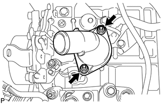
11. REMOVE WATER INLET
|
(a) Remove the 2 nuts and water inlet. |
|
12. REMOVE THERMOSTAT
(a) Remove the thermostat.
(b) Remove the gasket from the thermostat.
 Components
COMPONENTS
ILLUSTRATION
ILLUSTRATION
ILLUSTRATION
...
 Inspection
INSPECTION
PROCEDURE
1. INSPECT THERMOSTAT
HINT:
The valve opening temperature is inscribed on the thermostat.
(a) Immerse the thermostat in water, and then gradually heat the water. ...
Other materials about Toyota Venza:
System Description
SYSTEM DESCRIPTION
1. GENERAL
(a) This system uses ultrasonic sensors to detect any obstacles at the corners
and the rear of the vehicle. The system then informs the driver of the distance
between the sensors and an obstacle as well as their positions by ...
Data List / Active Test
DATA LIST / ACTIVE TEST
1. DATA LIST
HINT:
Using the Techstream to read the Data List allows the values or states of switches,
sensors, actuators and other items to be read without removing any parts. This non-intrusive
inspection can be very useful bec ...
System Diagram
SYSTEM DIAGRAM
Transmitting ECU (Transmitter)
Receiving ECU
Signal
Communication Method
Skid control ECU
Steering angle sensor
Steering angle sensor request signal
...

0.1245