Toyota Venza: TC and CG Terminal Circuit
DESCRIPTION
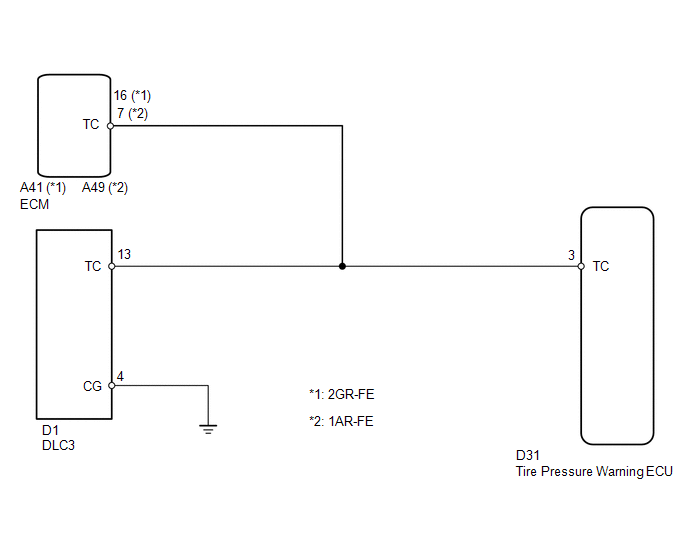
DTC output mode is set by connecting terminals 13 (TC) and 4 (CG) of the DLC3. The DTCs are indicated by the blinking pattern of the tire pressure warning light.
WIRING DIAGRAM
HINT:
When various warning lights blink continuously, a ground short in terminal TC of the DLC3 or an internal ground short in an ECU connected to this circuit may have occurred.
CAUTION / NOTICE / HINT
NOTICE:
- When replacing the tire pressure warning ECU, read the transmitter IDs stored in the old ECU using the Techstream and write them down before removal.
- It is necessary to perform registration (See page
.gif) ) of the transmitter IDs into the tire
) of the transmitter IDs into the tire
pressure warning ECU after the ECU has been replaced.
PROCEDURE
|
1. |
CHECK HARNESS AND CONNECTOR (DLC3 - TIRE PRESSURE WARNING ECU) |
|
(a) Disconnect the D31 ECU connector. |
|
(b) Measure the resistance according to the value(s) in the table below.
Standard Resistance:
|
Tester Connection |
Condition |
Specified Condition |
|---|---|---|
|
D31-3 (TC) - D1-13 (TC) |
Always |
Below 1 Ω |
|
D1-4 (CG) - Body ground |
|
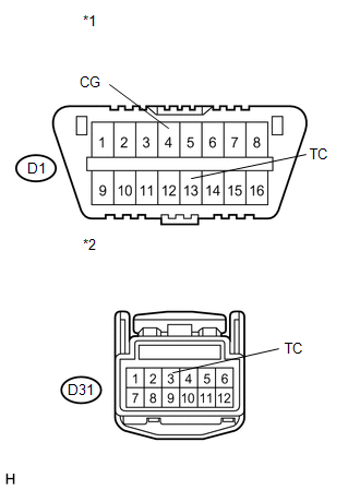
*1 |
Front view of wire harness connector (to DLC3) |
|
*2 |
Front view of wire harness connector (to Tire Pressure Warning ECU) |
| OK | .gif) |
PROCEED TO NEXT SUSPECTED AREA SHOWN IN PROBLEM SYMPTOMS TABLE |
| NG | |
REPAIR OR REPLACE HARNESS OR CONNECTOR |
 Tire Pressure Warning Light Circuit
DESCRIPTION
If the tire pressure warning ECU detects a malfunction, the tire pressure warning
light blinks for 1 minute then stays on and tire pressure monitor is canceled at
the same time. At th ...

Other materials about Toyota Venza:
Removal
REMOVAL
PROCEDURE
1. DISCONNECT CABLE FROM NEGATIVE BATTERY TERMINAL
CAUTION:
Wait at least 90 seconds after disconnecting the cable from the negative (-)
battery terminal to disable the SRS system.
NOTICE:
When disconnecting the cable, some systems ne ...
Data List / Active Test
DATA LIST / ACTIVE TEST
1. DATA LIST
HINT:
Using the Techstream to read the Data List allows the values or states of switches,
sensors, actuators and other items to be read without removing any parts. This non-intrusive
inspection can be very useful bec ...
Short to GND in Immobiliser System Power Source Circuit (B278A)
DESCRIPTION
This DTC is stored when the engine switch power source supply line is open or
shorted.
DTC No.
DTC Detection Condition
Trouble Area
B278A
Engine switch power source supply line is ope ...

0.1336