Toyota Venza: Inspection
INSPECTION
PROCEDURE
1. INSPECT FUEL INJECTOR ASSEMBLY
|
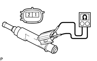
(a) Measure the resistance according to the value(s) in the table below. Standard Resistance:
If the result is not as specified, replace the fuel injector assembly. |
|
(b) Inspect the injector injection.
CAUTION:
Keep the injector away from sparks during the test.
|
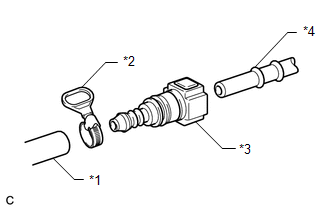
(1) Connect SST (fuel tube connector) to SST (hose) with SST (hose band), and then connect them to the fuel pipe (vehicle side). Text in Illustration
SST: 09268-31014 09268-41500 09268-41700 95336-08070 |
|
(2) Install a new O-ring to the fuel injector assembly.
|
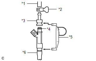
(3) Connect SST (adapter and hose) to the fuel injector assembly, and hold the fuel injector assembly and union with SST (clamp). Text in Illustration
SST: 09268-31014 09268-41110 09268-41300 09268-41700 95336-08070 |
|
(4) Install a vinyl tube onto the fuel injector assembly.
CAUTION:
Install a suitable vinyl tube onto the injector to contain any gasoline spray.
|
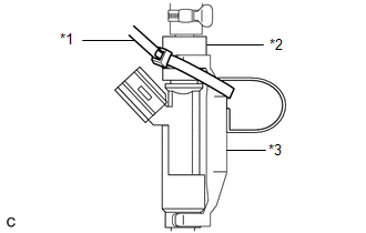
(5) Tie the clamp and adapter together with SST (tie band) as shown in the illustration. Text in Illustration
SST: 09268-31014 09268-41110 09268-41300 09268-41800 |
|
(6) Put the fuel injector assembly into a graduated cylinder.
(7) Operate the fuel pump (See page .gif) ).
).
|
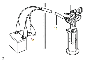
(8) Connect SST (wire) to the fuel injector assembly and the battery for 15 seconds, and measure the injection volume with the graduated cylinder. Test each fuel injector assembly 2 or 3 times. Text in Illustration
SST: 09842-30080 Standard Injection Volume:
Standard difference between each fuel injector assembly: 18 cc (1.1 cu. in.) or less If the result is not as specified, replace the fuel injector assembly. |
|
(c) Check for fuel drop.
(1) In the condition above, disconnect the tester probes of SST (wire) from the battery and check for fuel drop from the fuel injector assembly.
Standard fuel drop:
1 drop or less per 20 minutes
If fuel drop is not as specified, replace the fuel injector assembly.
 Removal
REMOVAL
CAUTION / NOTICE / HINT
HINT:
Perform "Inspection After Repair" after replacing the fuel injector assembly
(See page ).
PROCEDURE
1. DISCHARGE FUEL SYSTEM PRESSURE
(a) Disch ...
 Installation
INSTALLATION
PROCEDURE
1. INSTALL FUEL INJECTOR ASSEMBLY
HINT:
Perform "Inspection After Repair" after replacing the fuel injector assembly
(See page ).
(a) Apply a light ...
Other materials about Toyota Venza:
Transponder Chip Malfunction (B2793)
DESCRIPTION
This DTC is stored when a malfunction is found in the key during key code registration
or a key code is not registered normally. Replace the key if the key code registration
is not performed normally and this DTC is detected.
DTC N ...
Power Back Door Control Switch
Components
COMPONENTS
ILLUSTRATION
Inspection
INSPECTION
PROCEDURE
1. INSPECT POWER BACK DOOR OPENER / CLOSER SWITCH
(a) Measure the resistance of the switch.
Standard resistance:
Tester Connection
Condition
S ...
On-vehicle Inspection
ON-VEHICLE INSPECTION
PROCEDURE
1. INSPECT CAMSHAFT TIMING OIL CONTROL VALVE ASSEMBLY
(a) Connect the Techstream to the DLC3.
(b) Start the engine and turn the Techstream on.
(c) Inspect the oil control valve (for intake camshaft).
(1) Enter the followin ...

0.1476