Toyota Venza: Reassembly
REASSEMBLY
PROCEDURE
1. INSTALL NO. 2 STEERING RACK BOOT
|
(a) Apply lithium soap base glycol grease to the inside of the small opening of a new No. 2 steering rack boot. |
|
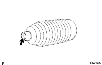
(b) Install the No. 2 steering rack boot to the groove on the rack housing.
NOTICE:
- Be careful not to damage or twist the boot.
- Make sure that the boot is free of rust and foreign matter.
2. INSTALL NO. 1 STEERING RACK BOOT
HINT:
Perform the same procedure as for the No. 2 steering rack boot.
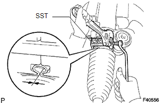
3. INSTALL NO. 2 STEERING RACK BOOT CLAMP
|
(a) Using SST, tighten a new No. 2 steering rack boot clamp as shown in the illustration. SST: 09521-24010 Clearance: 3.0 mm (0.118 in.) or less NOTICE: Be careful not to damage or twist the boot. |
|
4. INSTALL NO. 1 STEERING RACK BOOT CLAMP
HINT:
Perform the same procedure as for the No. 2 steering rack boot clamp.
SST: 09521-24010
5. INSTALL STEERING RACK BOOT CLIP (for LH Side)
(a) Using pliers, install the steering rack boot clip.
6. INSTALL STEERING RACK BOOT CLIP (for RH Side)
HINT:
Perform the same procedure as for the LH side.
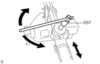
7. INSPECT STEERING GEAR ASSEMBLY
|
(a) Using SST, rotate the pinion shaft to see if both the left and the right steering rack boots expand and contract smoothly. SST: 09616-00020 HINT: If the operation cannot be done as specified, use new steering rack boot clamps and reinstall the steering rack boots. |
|
 Installation
INSTALLATION
CAUTION / NOTICE / HINT
NOTICE:
When disconnecting the steering intermediate shaft assembly and pinion shaft
of steering gear assembly, be sure to place matchmarks before servicing.
...

Other materials about Toyota Venza:
Power Window Motor Malfunction (B2311)
DESCRIPTION
The power window regulator motor is operated by the power window regulator master
switch assembly or power window regulator switch assembly. The power window regulator
motor assembly has motor, regulator and ECU functions.
This DTC is output ...
Reassembly
REASSEMBLY
PROCEDURE
1. INSTALL STIFFENING CRANKCASE RING PIN
NOTICE:
It is not necessary to remove the ring pin unless it is being replaced.
(a) Using a plastic-faced hammer, tap in 2 new ring pins until they stop.
Text in Illustration
...
Internal Control Module Throttle Position Performance (P060E)
MONITOR DESCRIPTION
The ECM monitors the input signals of the throttle position sensor No. 1 and
stop light switch. As the ECM monitors the input signals of the throttle position
sensor No. 1 and the STP signals of the stop light switch, if the input sign ...

0.1176