Toyota Venza: Reassembly
REASSEMBLY
PROCEDURE
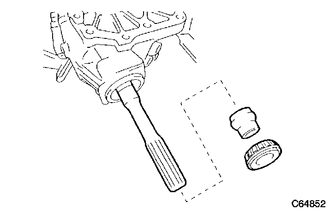
1. INSTALL TRANSFER DRIVEN PINION REAR BEARING
|
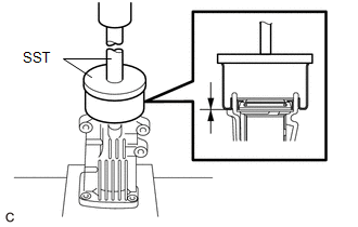
(a) Using SST and a press, press the transfer driven pinion rear bearing (outer race) to the case. SST: 09950-60010 09951-00620 SST: 09950-70010 09951-07150 NOTICE: Keep the transfer case horizontal using wooden blocks, etc. |
|
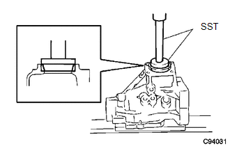
(b) Apply gear oil to the transfer driven pinion rear bearing (outer race).
2. INSTALL TRANSFER OUTPUT SHAFT WASHER
(a) Install the transfer output shaft washer to the transfer case.
HINT:
Install the same transfer output shaft washer as the one removed.
(b) Apply gear oil to the transfer output shaft washer.
3. INSTALL TRANSFER DRIVEN PINION FRONT BEARING
|
(a) Apply gear oil to the inner surface of the transfer case. |
|
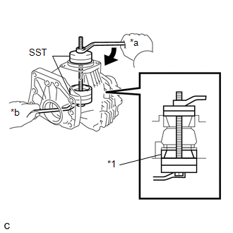
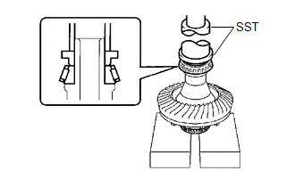
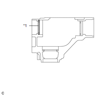
(b) Using SST, install the transfer driven pinion front bearing (outer race) to the transfer case.
SST: 09950-60010
09951-00610
09951-00620
09951-00650
SST: 09950-60020
09951-00680
Text in Illustration|
*1 |
Transfer Driven Pinion Front Bearing (Outer Race) |
|
*a |
Turn |
|
*b |
Hold |
|
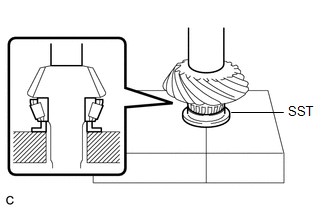
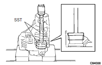
(c) Using SST and a press, press the transfer driven pinion front bearing (inner race) into the driven pinion. SST: 09506-30012 |
|
4. INSTALL DRIVEN PINION
|
(a) Install the driven pinion to the transfer case. |
|
|
(b) Install a new transfer pinion bearing spacer and the transfer driven pinion rear bearing (inner race) to the driven pinion. HINT: Install the transfer pinion bearing spacer with the larger inner diameter facing forward as shown in the illustration. |
|
|
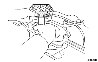
(c) Using SST, install a new gear nut. SST: 09326-20011 SST: 09556-16030 Torque: Specified tightening torque : 270-420 N·m {2753-4283 kgf·cm, 199-310 ft·lbf} Text in Illustration
NOTICE: Do not stake the gear nut until the final preload, tooth contact and backlash adjustments are completed. HINT:
|
|
5. ADJUST DRIVEN PINION PRELOAD
|
(a) Using SST and a torque wrench, measure the driven pinion preload. SST: 09326-20011 Text in Illustration
Specified Preload (at Starting):
NOTICE:
HINT:
|
|
6. INSTALL RING GEAR
(a) Clean the contact surfaces of the ring gear and transfer ring gear mounting case.
|
(b) Heat the ring gear in boiling water. Text in Illustration
|
|
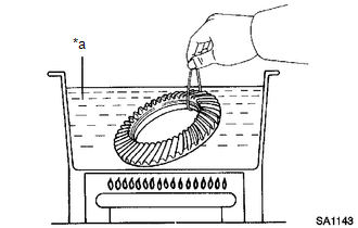
(c) Carefully remove the ring gear from the boiling water.
(d) Secure the transfer ring gear mounting case in a vise using aluminum plates.
NOTICE:
Be careful not to damage the transfer ring gear mounting case in the vise.
|
(e) After the moisture on the ring gear has completely evaporated, quickly align the matchmarks and set the ring gear to the transfer ring gear mounting case. Text in Illustration
|
|
.png)
(f) Apply adhesive to the 12 new bolts.
Adhesive:
Toyota Genuine Adhesive 1324, Three Bond 1324 or equivalent
(g) Install the 12 bolts.
Torque:
99 N·m {1005 kgf·cm, 73 ft·lbf}
NOTICE:
- Tighten the bolts evenly in a diagonal pattern using several steps.
- Tighten the bolts after the ring gear has cooled down sufficiently.
- In order to ensure proper sealing of the bolts, apply adhesive to the bolts and install them within 10 minutes of adhesive application.
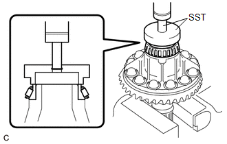
7. INSTALL RING GEAR MOUNTING CASE BEARING
|
(a) Using SST and a press, press the ring gear mounting case bearing (inner race) to the transfer ring gear mounting case. SST: 09387-00010 SST: 09950-70010 09951-07100 |
|
(b) Install the ring gear mounting case bearing (outer race) to the transfer ring gear mounting case.
(c) Apply gear oil to the ring gear mounting case bearing.
|
(d) Using SST and a press, press the ring gear mounting case bearing (inner race) to the transfer ring gear mounting case. SST: 09223-00010 SST: 09726-40010 |
|
(e) Install the ring gear mounting case plate washer to the case.
HINT:
If replacing the case plate washer, use one with the same thickness as the one removed.
|
(f) Using SST and a press, press the ring gear mounting case bearing (outer race) into the transfer case. SST: 09950-60010 09951-00680 SST: 09950-70010 09951-07200 |
|
(g) Apply gear oil to the ring gear mounting case bearing.
8. INSTALL TRANSFER RING GEAR MOUNTING CASE
|
(a) Apply gear oil to the transfer ring gear mounting case. |
|
.png)
(b) Install the transfer ring gear mounting case to the transfer case.
9. INSTALL NO. 1 TRANSFER OUTPUT SHAFT SPACER
|
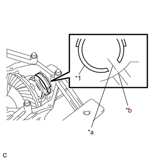
(a) Align the cutout on the No. 1 transfer output shaft spacer with the transfer case hole to install it as shown in the illustration. Text in Illustration
|
|
10. INSTALL NO. 2 TRANSFER RING GEAR MOUNTING CASE WASHER
|
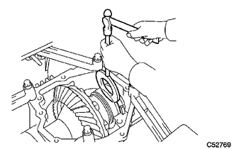
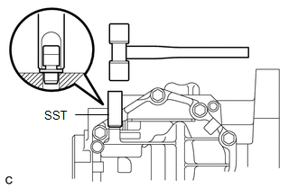
(a) Using a brass bar and a hammer, install the No. 2 transfer ring gear mounting case washer. HINT: Use a No. 2 transfer ring gear mounting case washer with the same thickness as the one removed. |
|
11. INSTALL BEARING CAP
|
(a) Install the bearing cap with the 2 bolts. Torque: 63 N·m {644 kgf·cm, 47 ft·lbf} |
|
.png)
12. INSPECT RING GEAR BACKLASH
|
(a) Set a dial indicator perpendicular to a ring gear tooth tip. Secure the driven pinion in place and move the ring gear back and forth to measure the backlash. Backlash: 0.14 to 0.25 mm (0.00551 to 0.00984 in.) NOTICE: Check at least 3 positions on the circumference of the ring gear. |
|
.png)
|
(b) If the backlash is outside the specified range, select a ring gear mounting case washer from the table and install it to meet the specified range. Text in Illustration
|
|
13. INSPECT TOOTH CONTACT BETWEEN RING GEAR AND DRIVEN PINION
|
(a) Coat 3 or 4 teeth at 4 different positions on the ring gear with Prussian blue. |
|
.png)
(b) Rotate the ring gear 10 times or more.
(c) Rotate the ring gear to inspect the tooth contact pattern.
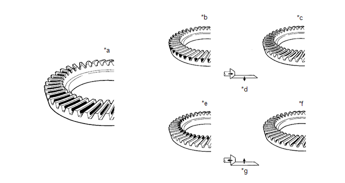 Text in Illustration
|
*a |
Proper Contact |
*b |
Heel Contact |
|
*c |
Face Contact |
*d |
Select a washer that will bring the driven pinion closer to the ring gear |
|
*e |
Toe Contact |
*f |
Flank Contact |
|
*g |
Select a washer that will shift the driven pinion away from the ring gear |
- |
- |
|
(d) If the tooth contact pattern is not correct, select a new transfer output shaft washer that is thicker or thinner as necessary and recheck. Text in Illustration
NOTICE: When the washer thickness is changed, readjust the backlash (See page
|
|
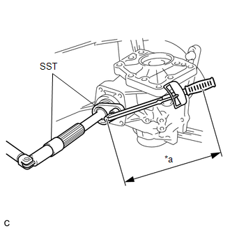
14. INSPECT AND ADJUST TOTAL PRELOAD
(a) Using SST and a torque wrench, measure the total preload.
SST: 09326-20011
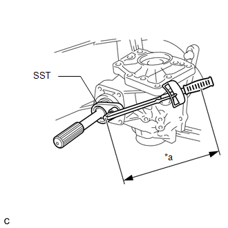 Text in Illustration
|
*a |
Torque Wrench Fulcrum Length |
Specified Total Preload (at Starting):
|
Item |
Preload |
|---|---|
|
New bearing |
0.48 to 0.70 N*m (5 to 7 kgf*cm, 5 to 6 in.*lbf) + Driven pinion preload |
|
Reused bearing |
0.35 to 0.53 N*m (4 to 5 kgf*cm, 4 to 4.6 in.*lbf) + Driven pinion preload |
NOTICE:
Turn the driven pinion counterclockwise and clockwise several times.
HINT:
- Calculate the torque wrench reading when changing the fulcrum length
of the torque wrench (See page
.gif) ).
).
- When using SST (fulcrum length of 50 mm (1.97 in.)) + torque wrench
(fulcrum length of 130 mm (5.12 ft.)):
Total Preload (at Starting):
Item
Preload
New bearing
0.35 to 0.50 N*m (4 to 5 kgf*cm, 4 to 4.4 in.*lbf) + Driven pinion preload
Reused bearing
0.25 to 0.38 N*m (3 to 3.8 kgf*cm, 3 to 3.3 in.*lbf) + Driven pinion preload
If the preload is outside the specified range, replace the No. 2 transfer ring gear mounting case washer with one that is thicker or thinner as necessary and recheck.
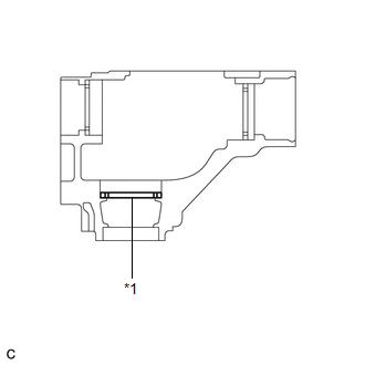
.png) Text in Illustration
Text in Illustration
|
*1 |
No. 2 Transfer Ring Gear Mounting Case Washer |
|
Mark |
Thickness (mm (in.)) |
Mark |
Thickness (mm (in.)) |
|---|---|---|---|
|
G7 |
2.47 (0.0972) |
M7 |
3.47 (0.1366) |
|
G8 |
2.49 (0.0980) |
M8 |
3.49 (0.1374) |
|
G9 |
2.51 (0.0988) |
M9 |
3.51 (0.1382) |
|
H0 |
2.53 (0.0996) |
N0 |
3.53 (0.1390) |
|
H1 |
2.55 (0.1004) |
N1 |
3.55 (0.1398) |
|
H2 |
2.57 (0.1012) |
N2 |
3.57 (0.1406) |
|
H3 |
2.59 (0.1020) |
N3 |
3.59 (0.1413) |
|
H4 |
2.61 (0.1028) |
N4 |
3.61 (0.1421) |
|
H5 |
2.63 (0.1035) |
N5 |
3.63 (0.1429) |
|
H6 |
2.65 (0.1043) |
N6 |
3.65 (0.1437) |
|
H7 |
2.67 (0.1051) |
N7 |
3.67 (0.1445) |
|
H8 |
2.69 (0.1059) |
N8 |
3.69 (0.1453) |
|
H9 |
2.71 (0.1067) |
N9 |
3.71 (0.1461) |
|
J0 |
2.73 (0.1075) |
P0 |
3.73 (0.1469) |
|
J1 |
2.75 (0.1083) |
P1 |
3.75 (0.1476) |
|
J2 |
2.77 (0.1091) |
P2 |
3.77 (0.1484) |
|
J3 |
2.79 (0.1098) |
P3 |
3.79 (0.1492) |
|
J4 |
2.81 (0.1106) |
P4 |
3.81 (0.1500) |
|
J5 |
2.83 (0.1114) |
P5 |
3.83 (0.1508) |
|
J6 |
2.85 (0.1122) |
P6 |
3.85 (0.1516) |
|
J7 |
2.87 (0.1130) |
P7 |
3.87 (0.1524) |
|
J8 |
2.89 (0.1138) |
P8 |
3.89 (0.1531) |
|
J9 |
2.91 (0.1146) |
P9 |
3.91 (0.1539) |
|
K0 |
2.93 (0.1154) |
Q0 |
3.93 (0.1547) |
|
K1 |
2.95 (0.1161) |
Q1 |
3.95 (0.1555) |
|
K2 |
2.97 (0.1169) |
Q2 |
3.97 (0.1563) |
|
K3 |
2.99 (0.1177) |
Q3 |
3.99 (0.1571) |
|
K4 |
3.01 (0.1185) |
Q4 |
4.01 (0.1579) |
|
K5 |
3.03 (0.1193) |
Q5 |
4.03 (0.1587) |
|
K6 |
3.05 (0.1201) |
Q6 |
4.05 (0.1594) |
|
K7 |
3.07 (0.1209) |
Q7 |
4.07 (0.1602) |
|
K8 |
3.09 (0.1217) |
Q8 |
4.09 (0.1610) |
|
K9 |
3.11 (0.1224) |
Q9 |
4.11 (0.1618) |
|
L0 |
3.13 (0.1232) |
R0 |
4.13 (0.1626) |
|
L1 |
3.15 (0.1240) |
R1 |
4.15 (0.1634) |
|
L2 |
3.17 (0.1248) |
R2 |
4.17 (0.1642) |
|
L3 |
3.19 (0.1256) |
R3 |
4.19 (0.1650) |
|
L4 |
3.21 (0.1264) |
R4 |
4.21 (0.1657) |
|
L5 |
3.23 (0.1272) |
R5 |
4.23 (0.1665) |
|
L6 |
3.25 (0.1280) |
R6 |
4.25 (0.1673) |
|
L7 |
3.27 (0.1287) |
R7 |
4.27 (0.1681) |
|
L8 |
3.29 (0.1295) |
R8 |
4.29 (0.1689) |
|
L9 |
3.31 (0.1303) |
R9 |
4.31 (0.1697) |
|
M0 |
3.33 (0.1311) |
S0 |
4.33 (0.1705) |
|
M1 |
3.35 (0.1319) |
S1 |
4.35 (0.1713) |
|
M2 |
3.37 (0.1327) |
S2 |
4.37 (0.1720) |
|
M3 |
3.39 (0.1335) |
S3 |
4.39 (0.1728) |
|
M4 |
3.41 (0.1343) |
S4 |
4.41 (0.1736) |
|
M5 |
3.43 (0.1350) |
S5 |
4.43 (0.1744) |
|
M6 |
3.45 (0.1358) |
S6 |
4.45 (0.1752) |
|
(b) Using a chisel and a hammer, stake the gear nut. |
|
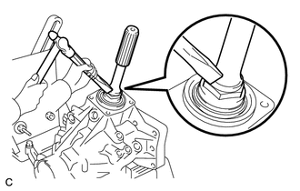
15. INSTALL TRANSFER CASE FRONT OIL SEAL (for RH Side)
|
(a) Using SST and a hammer, drive a new transfer case front oil seal into the case until it reaches the position shown in the illustration. SST: 09950-60010 09951-00350 09951-00580 09952-06010 SST: 09950-70010 09951-07150 Drive in depth: 33.5 to 34.5 mm (1.319 to 1.358 in.) NOTICE: Make sure that the transfer case front oil seal is not tilted. |
|
(b) Apply a small amount of MP grease to the lip of the transfer case front oil seal.
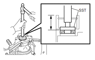
16. INSTALL TRANSFER CASE FRONT OIL SEAL
|
(a) Using SST and a hammer, drive a new transfer case front oil seal into the transfer case until it reaches the position in the illustration. SST: 09608-10010 SST: 09950-70010 09951-07150 Drive in depth: 9.5 to 10.5 mm (0.374 to 0.413 in.) |
|
(b) Apply a small amount of MP grease to the lip of the transfer case front oil seal.
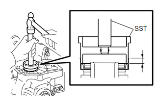
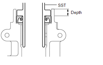
17. INSTALL TRANSFER CASE REAR OIL SEAL
|
(a) Using SST and a hammer, drive a new transfer case rear oil seal into the extension housing until it reaches the position shown in the illustration. SST: 09325-20010 Drive in depth: 9.8 to 10.6 mm (0.386 to 0.417 in.) |
|
(b) Apply a small amount of MP grease to the lip of the transfer case rear oil seal.
18. INSTALL TRANSFER EXTENSION HOUSING DUST DEFLECTOR
|
(a) Using SST and a press, press in a new transfer extension housing dust deflector until it contacts the installation surface as shown in the illustration. SST: 09950-60020 09951-01030 SST: 09950-70010 09951-07150 |
|
19. INSTALL TRANSFER EXTENSION HOUSING SUB-ASSEMBLY
|
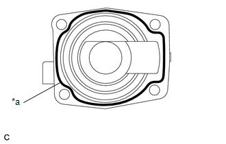
(a) Remove any FIPG material and be careful not to drop oil on the contact surfaces of the transfer extension housing sub-assembly and the transfer case. Text in Illustration
|
|
(b) Degrease the surfaces with a non-residue solvent.
(c) Apply FIPG to the transfer extension housing sub-assembly.
FIPG:
Toyota Genuine Seal Packing 1281, Three Bond 1281 or equivalent
|
(d) Install the transfer extension housing sub-assembly with the 4 bolts to the transfer case. Torque: 26 N·m {260 kgf·cm, 19 ft·lbf} NOTICE: Assemble the transfer extension housing sub-assembly within 10 minutes of FIPG application. |
|
20. SEPARATE TRANSFER ASSEMBLY
(a) Remove the transfer assembly from the overhaul attachment.
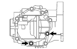
21. INSTALL TRANSFER CASE STRAIGHT PIN
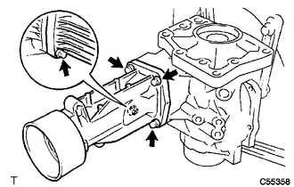
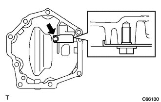
(a) Using a plastic hammer, drive the 4 transfer case straight pins into the transfer case positions shown in the illustration.
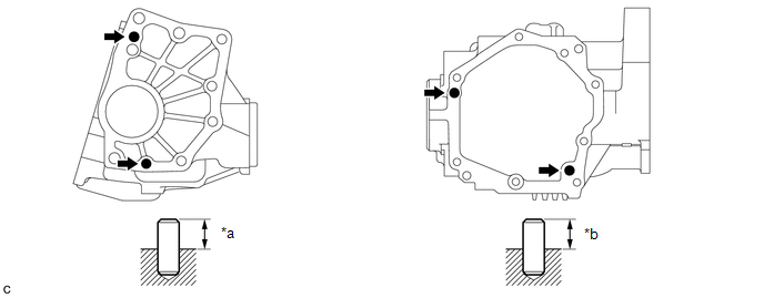 Text in Illustration
|
*a |
10.8 to 11.8 mm (0.425 to 0.465 in.) |
*b |
5.7 to 6.7 mm (0.224 to 0.264 in.) |
22. INSTALL TRANSFER DYNAMIC DAMPER (for 1AR-FE)
|
(a) Install the transfer dynamic damper with the 3 bolts to the transfer extension housing sub-assembly. Torque: 26 N·m {260 kgf·cm, 19 ft·lbf} |
|
.png)
23. INSTALL TRANSFER CASE BREATHER PLUG
|
(a) Using SST and a hammer, tap in a new transfer case breather plug. SST: 09820-00031 |
|
24. INSTALL BREATHER OIL DEFLECTOR
|
(a) Install the breather oil deflector with the bolt. Torque: 6.5 N·m {66 kgf·cm, 58 in·lbf} |
|
25. INSTALL NO. 1 TRANSFER CASE COVER
|
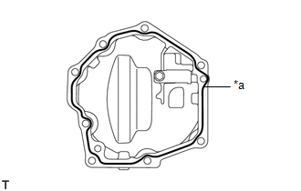
(a) Remove any FIPG material and be careful not to drop oil on the contact surfaces of the No. 1 transfer case cover and the transfer case. Text in Illustration
|
|
(b) Degrease the surfaces with a non-residue solvent.
(c) Apply FIPG to the No. 1 transfer case cover.
FIPG:
Toyota Genuine Seal Packing 1281, Three Bond 1281 or equivalent
|
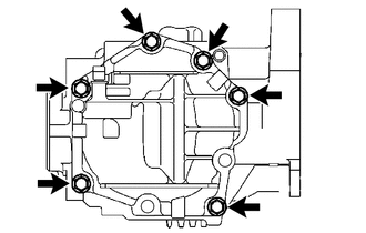
(d) Install the No. 1 transfer case cover with the 6 bolts. Torque: 20 N·m {200 kgf·cm, 14 ft·lbf} NOTICE:
|
|
|
(e) Install the No. 1 transfer case cover with 2 new bolts. Torque: 20 N·m {200 kgf·cm, 14 ft·lbf} |
|
26. INSTALL TRANSFER DRAIN PLUG
|
(a) Install a new gasket to the transfer drain plug. |
|
.png)
(b) Install the transfer drain plug to the transfer assembly.
Torque:
49 N·m {500 kgf·cm, 36 ft·lbf}
27. INSTALL NO. 1 TRANSFER CASE PLUG
|
(a) Install a new gasket to the No. 1 transfer case plug. |
|
.png)
(b) Install the No. 1 transfer case plug to the transfer assembly.
Torque:
49 N·m {500 kgf·cm, 36 ft·lbf}
28. INSTALL NO. 2 TRANSFER CASE PLUG
|
(a) Install a new gasket to the No. 2 transfer case plug. |
|
.png)
(b) Install the No. 2 transfer case plug to the transfer assembly.
Torque:
49 N·m {500 kgf·cm, 36 ft·lbf}
29. INSTALL TRANSFER AND TRANSAXLE SETTING STUD BOLT
(a) Install 4 new transfer and transaxle setting stud bolts to the transfer case positions shown in the illustration.
Torque:
Stud Bolt (A) :
39.2 N·m {400 kgf·cm, 29 ft·lbf}
Stud Bolt (B) :
25 N·m {255 kgf·cm, 18 ft·lbf}
HINT:
Install the shorter end of the stud bolts to the transfer assembly.
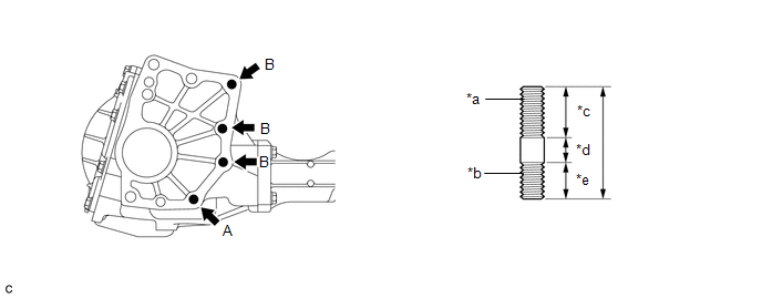 Text in Illustration
|
*a |
Transaxle Side |
*b |
Transfer Side |
|
*c |
30 mm (1.1811 in.) |
*d |
12 mm (0.4724 in.) |
|
*e |
22 mm (0.8661 in.) |
- |
- |
 Inspection
INSPECTION
PROCEDURE
1. INSPECT PRELOAD
(a) Using SST and a torque wrench, measure the preload of the backlash
between the driven pinion and ring gear.
SST: 09326-20011
Preload ...
 Installation
INSTALLATION
PROCEDURE
1. INSTALL TRANSFER ASSEMBLY
(a) Install the transfer assembly to the transaxle assembly with 2 new
bolts and the 6 nuts.
Torque:
69 N·m {700 kgf·cm, ...
Other materials about Toyota Venza:
Components
COMPONENTS
ILLUSTRATION
ILLUSTRATION
ILLUSTRATION
ILLUSTRATION
ILLUSTRATION
ILLUSTRATION
...
Precaution
PRECAUTION
1. PRECAUTION FOR DISCONNECTING CABLE FROM NEGATIVE BATTERY TERMINAL
NOTICE:
After the ignition switch is turned off, the navigation receiver assembly
records various types of memory and settings. As a result, after turning
the ig ...
On-vehicle Inspection
ON-VEHICLE INSPECTION
PROCEDURE
1. CHECK STEERING EFFORT (TORQUE)
NOTICE:
Some of these service operations may affect the SRS airbags. Read the precautionary
notices concerning the SRS airbag system before servicing.
(a) Stop the vehicle on a level, pav ...

0.1306