Toyota Venza: Power Source Circuit
DESCRIPTION
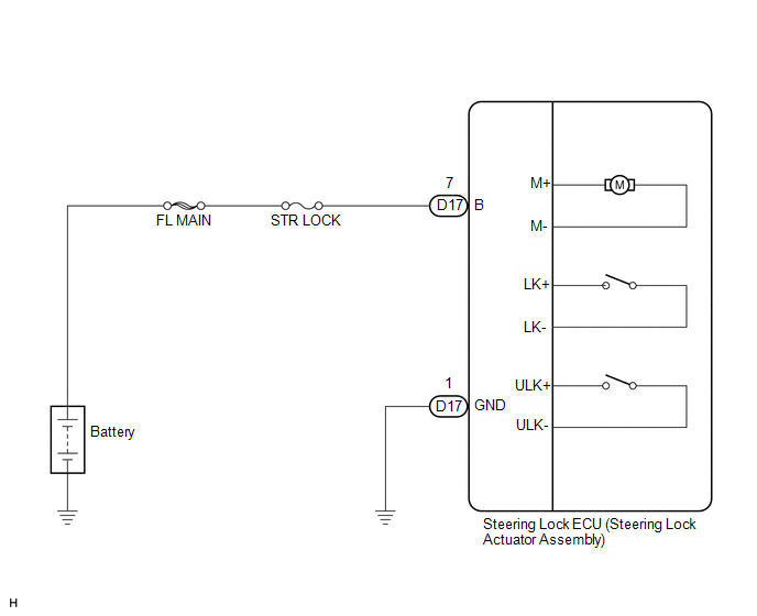
This circuit supplies power source voltage from the battery to terminal B of the steering lock ECU (steering lock actuator assembly). This is used as power source for the CPU, motor, communication, and peripheral circuits.
WIRING DIAGRAM
PROCEDURE
|
1. |
CHECK HARNESS AND CONNECTOR (STEERING LOCK ECU - BODY GROUND) |
|
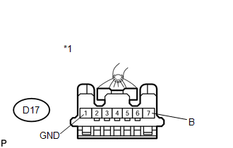
(a) Disconnect the D17 connector from the steering lock ECU (steering lock actuator assembly). |
|
.png)
(b) Measure the resistance according to the value(s) in the table below.
Standard Resistance:
|
Tester Connection |
Condition |
Specified Condition |
|---|---|---|
|
D17-1 (GND) - Body ground |
Always |
Below 1 Ω |
|
*1 |
Front view of wire harness connector (to Steering lock ECU (Steering lock actuator assembly)) |
| NG | .gif) |
REPAIR OR REPLACE HARNESS OR CONNECTOR |
|
.gif)
|
2. |
CHECK HARNESS AND CONNECTOR (STEERING LOCK ECU - BATTERY) |
|
(a) Measure the voltage according to the value(s) in the table below. Standard Voltage:
|
|
| OK | |
PROCEED TO NEXT SUSPECTED AREA SHOWN IN PROBLEM SYMPTOMS TABLE |
| NG | |
REPAIR OR REPLACE HARNESS OR CONNECTOR (STEERING LOCK ECU - BATTERY) |
 Unlock Position Sensor Signal Circuit
DESCRIPTION
The unlock position sensor is one of the components comprising the steering lock
ECU (steering lock actuator assembly). The sensor switch contact closes when the
steering lock is rele ...
 Steering System
...
Other materials about Toyota Venza:
Installation
INSTALLATION
PROCEDURE
1. INSTALL BRAKE MASTER CYLINDER SUB-ASSEMBLY
NOTICE:
When install a new brake master cylinder sub-assembly, remove the protectors
from the piston and outlet ports.
(a) Install a new O-ring to the brake master cylinder sub-assembl ...
Problem Symptoms Table
PROBLEM SYMPTOMS TABLE
HINT:
Use the table below to help determine the cause of problem symptoms. If multiple
suspected areas are listed, the potential causes of the symptoms are listed in order
of probability in the "Suspected Area" column of ...
Multi-information display (TFT type)
The multi-information display presents the driver with a variety of driving-related
data, including the clock and current outside temperature.
• Clock
Indicates and sets the time.
• Outside temperature
Indicates the outside temperature.
The temper ...

0.1168