Toyota Venza: Room Light
Components
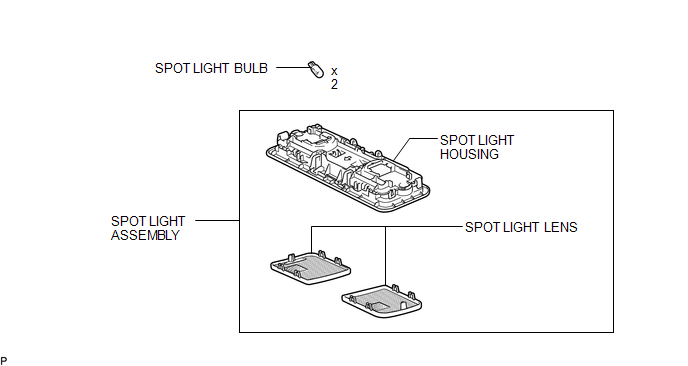
COMPONENTS
ILLUSTRATION
Removal
REMOVAL
PROCEDURE
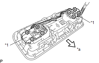
1. REMOVE SPOT LIGHT ASSEMBLY
|
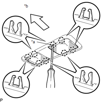
(a) Using a screwdriver with its tip wrapped with protective tape, disengage the 8 claws to remove the 2 spot light lenses. Text in Illustration
|
|
|
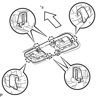
(b) Using a screwdriver with its tip wrapped with protective tape and moulding remover, disengage the 2 claws (A). Text in Illustration
|
|
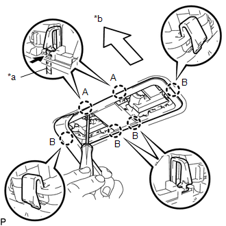
(c) Disengage the 4 claws (B) and disconnect the spot light housing.
|
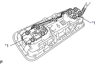
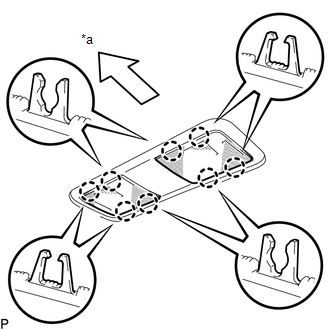
(d) Using a screwdriver, disengage the 8 claws and clamp to remove the spot light housing from the 2 map light sub-assemblies. Text in Illustration
|
|
2. REMOVE SPOT LIGHT BULB
(a) Remove the 2 spot light bulbs from the 2 map light sub-assemblies.
Installation
INSTALLATION
PROCEDURE
1. INSTALL SPOT LIGHT BULB
(a) Install the 2 spot light bulbs to the 2 map light sub-assemblies.
2. INSTALL SPOT LIGHT ASSEMBLY
|
(a) Engage the 8 claws and clamp to connect the spot light housing to the 2 map light sub-assemblies as shown in the illustration. Text in Illustration
|
|
|
(b) Engage the 6 claws to install the spot light housing. Text in Illustration
|
|
|
(c) Engage the 8 claws to install the 2 spot light lenses. Text in Illustration
|
|
 Relay
Relay
On-vehicle Inspection
ON-VEHICLE INSPECTION
PROCEDURE
1. INSPECT DOME CUT RELAY
(a) Measure the resistance according to the value(s) in the table below.
Standard Resistance:
...
 Vanity Light
Components
COMPONENTS
ILLUSTRATION
Installation
INSTALLATION
PROCEDURE
1. INSTALL VANITY LIGHT ASSEMBLY
(a) Engage the 3 claws and install the vanity light assembly.
...
Other materials about Toyota Venza:
Disassembly
DISASSEMBLY
PROCEDURE
1. REMOVE BRAKE MASTER CYLINDER RESERVOIR ASSEMBLY
(a) Mount the brake master cylinder sub-assembly in a vise.
NOTICE:
Place aluminum plates on the vise to prevent damage to the brake master cylinder
sub-assembly.
(b) U ...
Front Occupant Classification Sensor RH Circuit Malfunction (B1781)
DESCRIPTION
The front occupant classification sensor RH circuit consists of the occupant
classification ECU and front occupant classification sensor RH.
DTC B1781 is recorded when a malfunction is detected in the front occupant classification
sensor RH c ...
Stereo Jack Adapter Assembly
Components
COMPONENTS
ILLUSTRATION
Removal
REMOVAL
PROCEDURE
1. REMOVE UPPER CONSOLE PANEL SUB-ASSEMBLY (w/o Seat Heater System)
2. REMOVE UPPER CONSOLE PANEL SUB-ASSEMBLY (w/ Seat Heater System)
3. REMOVE NO. 2 CONSOLE BOX CARPET
4. RE ...

0.1309