Toyota Venza: Vsc Off Switch
Components
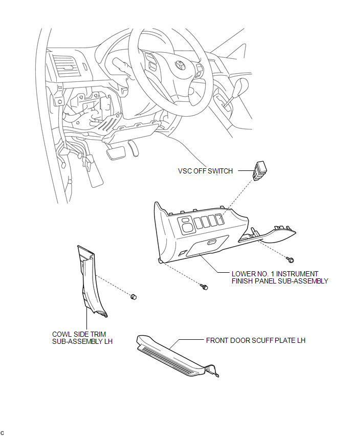
COMPONENTS
ILLUSTRATION
Removal
REMOVAL
PROCEDURE
1. DISCONNECT CABLE FROM NEGATIVE BATTERY TERMINAL
NOTICE:
When disconnecting the cable, some systems need to be initialized after the cable
is reconnected (See page .gif) ).
).
2. REMOVE FRONT DOOR SCUFF PLATE LH
3. REMOVE COWL SIDE TRIM SUB-ASSEMBLY LH
4. REMOVE LOWER NO. 1 INSTRUMENT FINISH PANEL SUB-ASSEMBLY
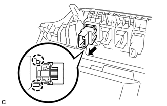
5. REMOVE VSC OFF SWITCH
|
(a) Disengage the 2 claws and remove the VSC OFF switch. |
|
Inspection
INSPECTION
PROCEDURE
1. INSPECT VSC OFF SWITCH
(a) Disconnect the VSC OFF switch connector.
|
(b) Measure the resistance according to the value(s) in the table below. Standard Resistance:
If the value is not as specified, replace the VSC OFF switch. |
|
.png)
Installation
INSTALLATION
PROCEDURE
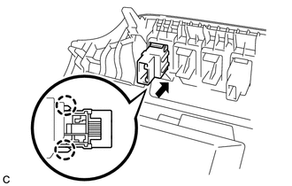
1. INSTALL VSC OFF SWITCH
|
(a) Engage the 2 claws and install the VSC OFF switch. |
|
2. INSTALL LOWER NO. 1 INSTRUMENT FINISH PANEL SUB-ASSEMBLY
.gif)
3. INSTALL COWL SIDE TRIM SUB-ASSEMBLY LH
4. INSTALL FRONT DOOR SCUFF PLATE LH
5. CONNECT CABLE TO NEGATIVE BATTERY TERMINAL
NOTICE:
When disconnecting the cable, some systems need to be initialized after the cable
is reconnected (See page ).
6. CHECK FOR WARNING LIGHT AND INDICATOR LIGHT
HINT:
(See page ).
 TS and CG Terminal Circuit
DESCRIPTION
In the Test Mode (signal check), a malfunction in the speed sensor that cannot
be detected when the vehicle is stopped can be detected while driving.
Transition to the sensor check mod ...

Other materials about Toyota Venza:
Installation
INSTALLATION
CAUTION / NOTICE / HINT
HINT:
Use the same procedure for the RH side and LH side.
The procedure listed below is for the LH side.
PROCEDURE
1. INSTALL REAR AXLE HUB AND BEARING ASSEMBLY
(a) Install the parking bra ...
Inspection
INSPECTION
PROCEDURE
1. INSPECT BRAKE VACUUM CHECK VALVE ASSEMBLY
(a) Check that there is ventilation from the booster to the engine, and
no ventilation from the engine to the booster.
If the results are not as specified, replace the brake ...
Inner Rear View Mirror Power Source Circuit
DESCRIPTION
This circuit detects the state of the ignition switch, and sends it to the inner
rear view mirror assembly.
WIRING DIAGRAM
CAUTION / NOTICE / HINT
NOTICE:
Inspect the fuses for circuits related to this system before performing the followin ...

0.1313