Toyota Venza: Data Signal Circuit between Radio Receiver and Extension Module
DESCRIPTION
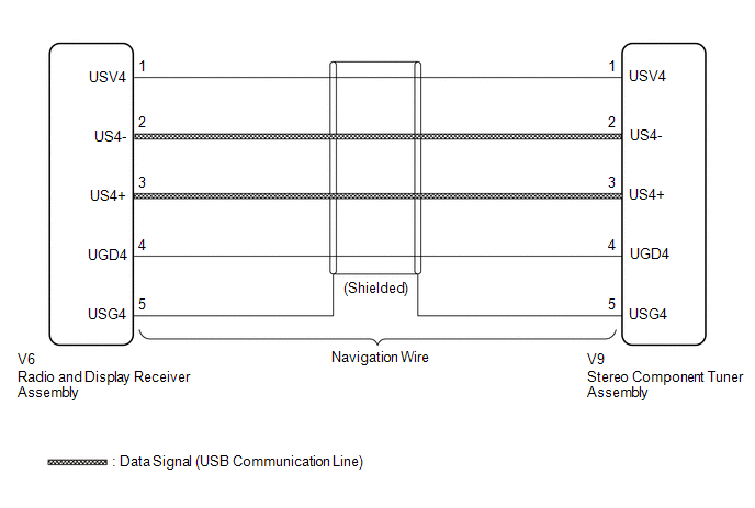
The stereo component tuner assembly sends the image data signal to the radio and display receiver assembly via this circuit.
WIRING DIAGRAM
PROCEDURE
|
1. |
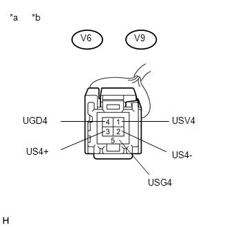
CHECK NAVIGATION WIRE |
(a) Remove the navigation wire (See page .gif) ).
).
|
(b) Measure the resistance according to the value(s) in the table below. Standard Resistance:
|
|
| OK | .gif) |
PROCEED TO NEXT SUSPECTED AREA SHOWN IN PROBLEM SYMPTOMS TABLE |
| NG | |
REPLACE NAVIGATION WIRE |
 Data Signal Circuit between Radio Receiver and Stereo Jack Adapter
DESCRIPTION
The No. 1 stereo jack adapter assembly sends the sound data signal or image data
signal from a USB device to the radio and display receiver assembly via this circuit.
WIRING DIAGRAM
...
 Reverse Signal Circuit
DESCRIPTION
The radio and display receiver assembly receives a reverse signal from the park/neutral
position switch assembly.
WIRING DIAGRAM
PROCEDURE
1.
CHECK BACK-UP L ...
Other materials about Toyota Venza:
Headlight Beam Level Control Actuator Circuit
DESCRIPTION
The headlight leveling ECU assembly actuates the headlight leveling motor according
to vehicle conditions.
WIRING DIAGRAM
PROCEDURE
1.
READ VALUE USING TECHSTREAM
(a) Connect the Techstream to the DLC3.
(b) ...
Installation
INSTALLATION
PROCEDURE
1. INSTALL PARK/NEUTRAL POSITION SWITCH ASSEMBLY
(a) Move the shift lever to N.
(b) Align the protrusions of the park/neutral position switch.
Text in Illustration
*1
Protrusion
...
Installation
INSTALLATION
PROCEDURE
1. INSTALL REAR DOOR BELT MOULDING
(a) Engage the 5 claws to install the rear door belt moulding.
2. INSTALL REAR DOOR GLASS SUB-ASSEMBLY
3. INSTALL REAR DOOR WINDOW DIVIS ...

0.1574