Toyota Venza: Transfer Case Front Oil Seal(when Not Using The Engine Support Bridge)
Components
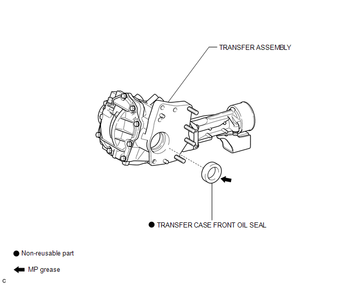
COMPONENTS
ILLUSTRATION
Replacement
REPLACEMENT
PROCEDURE
1. REMOVE TRANSFER ASSEMBLY
(See page .gif) ).
).
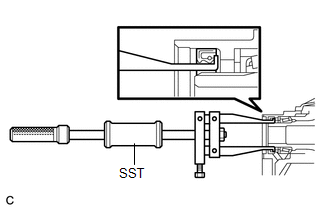
2. REMOVE TRANSFER CASE FRONT OIL SEAL
|
(a) Using SST, remove the transfer case front oil seal from the transfer case. SST: 09308-00010 NOTICE: Do not damage the oil seal contact surface on the case. |
|
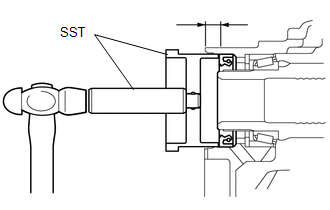
3. INSTALL TRANSFER CASE FRONT OIL SEAL
|
(a) Using SST, drive in a new transfer case front oil seal into the transfer case until it reaches the position shown in the illustration. SST: 09608-10010 SST: 09950-70010 09951-07150 Drive in depth: 9.5 to 10.5 mm (0.374 to 0.413 in.) NOTICE: Do not tilt the oil seal during installation. |
|
(b) Apply a small amount of MP grease to the lip of the oil seal.
4. INSTALL TRANSFER ASSEMBLY
(See page ).
 Installation
INSTALLATION
PROCEDURE
1. INSTALL TRANSFER ASSEMBLY
(a) Install the transfer assembly to the automatic transaxle assembly
with 2 new bolts and the 6 nuts.
Torque:
69 N·m {700 ...
 Transfer Case Front Oil Seal(when Using The Engine Support Bridge)
Components
COMPONENTS
ILLUSTRATION
Replacement
REPLACEMENT
PROCEDURE
1. REMOVE TRANSFER ASSEMBLY
See page
2. REMOVE TRANSFER CASE FRONT OIL SEAL
(a) Using SST, remove the t ...
Other materials about Toyota Venza:
Removal
REMOVAL
PROCEDURE
1. REMOVE REAR SEAT HEADREST ASSEMBLY
2. REMOVE REAR SEAT CENTER HEADREST ASSEMBLY
3. REMOVE REAR SEAT INNER TRACK BRACKET COVER
4. REMOVE REAR SEAT OUTER TRACK BRACKET COVER
5. DISCONNECT REAR SEAT RECLINING CONTROL CABLE S ...
Disassembly
DISASSEMBLY
PROCEDURE
1. REMOVE STEERING RACK BOOT CLIP (for LH Side)
(a) Using pliers, remove the steering rack boot clip.
2. REMOVE STEERING RACK BOOT CLIP (for RH Side)
HINT:
Perform the same procedure as for the LH side.
3. REMOVE NO. 2 STEERING RAC ...
How To Proceed With Troubleshooting
CAUTION / NOTICE / HINT
HINT:
Use the following procedure to troubleshoot the engine immobiliser system.
*: Use the Techstream.
PROCEDURE
1.
VEHICLE BROUGHT TO WORKSHOP
NEXT
...

0.1297