Toyota Venza: Transponder Key Ecu
Components
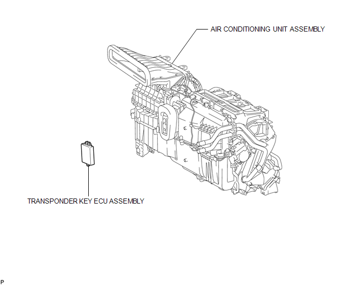
COMPONENTS
ILLUSTRATION
Removal
REMOVAL
PROCEDURE
1. REMOVE AIR CONDITIONING UNIT ASSEMBLY
HINT:
Refer to the procedure up to Remove Air Conditioning Unit Assembly (See page
.gif) ).
).
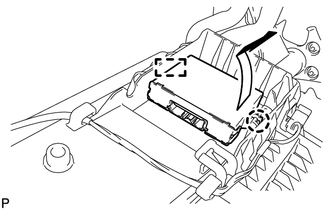
2. REMOVE TRANSPONDER KEY ECU ASSEMBLY
|
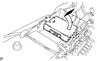
(a) Disengage the claw and guide and remove the transponder key ECU assembly. |
|
Installation
INSTALLATION
PROCEDURE
1. INSTALL TRANSPONDER KEY ECU ASSEMBLY
|
(a) Engage the guide and claw and install the transponder key ECU assembly. |
|
2. INSTALL AIR CONDITIONING UNIT ASSEMBLY
HINT:
Refer to the procedure from Install Air Conditioning Unit Assembly (See page
.gif) ).
).
3. REGISTER KEY
NOTICE:
When replacing the transponder key ECU assembly, perform initialization (See
page ).
 Transponder Key Amplifier
Components
COMPONENTS
ILLUSTRATION
Removal
REMOVAL
PROCEDURE
1. REMOVE FRONT DOOR SCUFF PLATE
2. REMOVE COWL SIDE TRIM SUB-ASSEMBLY
3. REMOVE LOWER NO. 1 INSTRUMENT PANEL FINISH PA ...
Other materials about Toyota Venza:
Fuel Tank Cap
Inspection
INSPECTION
PROCEDURE
1. INSPECT FUEL TANK CAP ASSEMBLY
(a) Visually check that the fuel tank cap assembly and gasket are not
deformed or damaged.
Text in Illustration
*a
Gasket
...
Replacement
REPLACEMENT
PROCEDURE
1. RECOVER REFRIGERANT FROM REFRIGERATION SYSTEM
(a) Start up the engine.
(b) Turn the A/C switch on.
(c) Operate the cooler compressor at an engine speed of approximately 1000 rpm
for 5 to 6 minutes to circulate the refrigerant. T ...
Removal
REMOVAL
PROCEDURE
1. REMOVE REAR DOOR SCUFF PLATE
2. DISCONNECT REAR DOOR OPENING TRIM WEATHERSTRIP
(a) Remove the rear part of the rear door opening trim weatherstrip to
the extent that allows removal of the deck trim side panel assembly ...

0.1715