
Toyota Venza: Transmitter Battery(w/ Smart Key System)
Replacement
REPLACEMENT
PROCEDURE
1. REMOVE TRANSMITTER BATTERY
NOTICE:
Take extra care when handling these precision electronic components.
|
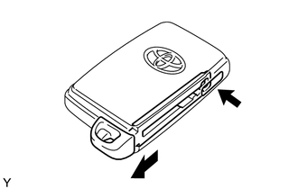
(a) Push the release hook knob and extract the mechanical key. |
|
|
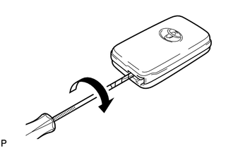
(b) Insert a precision screwdriver into the gap, and turn the screwdriver to detach the transmitter housing cover. HINT: Tape the screwdriver tip before use. |
|
|
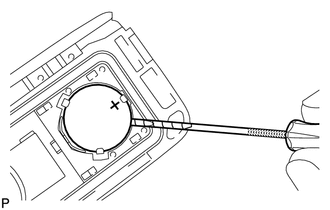
(c) Insert a precision screwdriver into the gap and gently remove the battery (lithium battery: CR1632). NOTICE:
HINT: Tape the screwdriver tip before use. |
|
2. INSTALL TRANSMITTER BATTERY
|
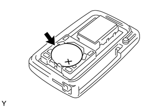
(a) Install a new battery (lithium battery: CR1632) with the positive (+) side facing upward, as shown in the illustration. NOTICE:
|
|
|
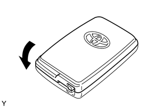
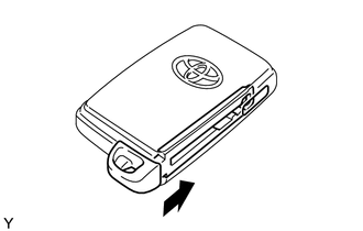
(b) Install the transmitter housing cover by pressing down on it as shown in the illustration. |
|
|
(c) Insert the mechanical key into the transmitter. |
|
(d) Press one of the transmitter switches and check that the LED illuminates.
OK:
Transmitter LED illuminates when switch is pressed.
 Installation
INSTALLATION
PROCEDURE
1. INSTALL REAR DOOR LOCK ASSEMBLY
NOTICE:
When reusing the removed rear door lock assembly, replace the door lock
wiring harness seal on the connector with a ne ...
 Transmitter Battery(w/o Smart Key System)
Replacement
REPLACEMENT
PROCEDURE
1. REMOVE TRANSMITTER HOUSING COVER
(a) Using a precision screwdriver with its tip wrapped in protective
tape, pry open the transmitter housing c ...
Other materials about Toyota Venza:
Diagnostic Trouble Code Chart
DIAGNOSTIC TROUBLE CODE CHART
HINT:
If a trouble code is displayed during the DTC check, inspect the trouble areas
listed for that code. For details of the code, refer to the following "See page".
Back Door Closer System
DTC Code
...
Adjustment
ADJUSTMENT
CAUTION / NOTICE / HINT
CAUTION:
Before adjusting the door positions of vehicles equipped with side and curtain
shield airbags, be sure to disconnect the battery. After adjustment, check that
the SRS warning light is operating normally and ...
Diagnostic Trouble Code Chart
DIAGNOSTIC TROUBLE CODE CHART
Lighting System
DTC Code
Detection Item
See page
B1244
Light Sensor Circuit Malfunction
B124D
Lost Communication with AFS LIN
...

0.1372