Toyota Venza: Transmission Wire(when Using The Engine Support Bridge)
Components
COMPONENTS
ILLUSTRATION
Installation
INSTALLATION
PROCEDURE
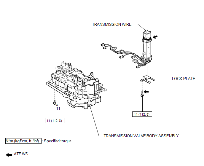
1. INSTALL TRANSMISSION WIRE
|
(a) Coat the O-ring with ATF. |
|
.png)
(b) Coat the bolt with ATF.
(c) Install the transmission wire and lock plate to the transmission valve body assembly with the bolt.
Torque:
11 N·m {112 kgf·cm, 8 ft·lbf}
(d) Engage the clamp.
(e) Connect the 8 shift solenoid valve connectors.
(f) Connect the speed sensor connector.
2. INSTALL TRANSMISSION VALVE BODY ASSEMBLY
See page .gif)
Removal
REMOVAL
PROCEDURE
1. REMOVE TRANSMISSION VALVE BODY ASSEMBLY
See page .gif)
2. REMOVE TRANSMISSION WIRE
|
(a) Disconnect the speed sensor connector. |
|
.png)
(b) Disconnect the 8 shift solenoid valve connectors.
(c) Disengage the clamp.
|
(d) Remove the bolt, lock plate and transmission wire from the transmission valve body assembly. |
|
.png)
 Transmission Wire(when Not Using The Engine Support Bridge)
Components
COMPONENTS
ILLUSTRATION
Installation
INSTALLATION
PROCEDURE
1. INSTALL TRANSMISSION WIRE
(a) Coat the O-ring with ATF.
...

Other materials about Toyota Venza:
Initialization
INITIALIZATION
1. INITIALIZE SLIDING ROOF ECU (SLIDING ROOF DRIVE GEAR SUB-ASSEMBLY)
NOTICE:
When the sliding roof glass, sliding roof housing or sliding roof ECU
(sliding roof drive gear sub-assembly) is replaced or removed and installed,
t ...
Installation
INSTALLATION
CAUTION / NOTICE / HINT
NOTICE:
When disconnecting the steering intermediate shaft assembly and pinion shaft
of steering gear assembly, be sure to place matchmarks before servicing.
PROCEDURE
1. INSTALL TIE ROD ASSEMBLY LH
(a) I ...
Reassembly
REASSEMBLY
PROCEDURE
1. INSTALL SHIFT LOCK CONTROL COMPUTER SUB-ASSEMBLY
(a) Engage the 3 claws to install the shift lock control computer sub-assembly.
(b) Connect the connector.
2. INSTALL LOWER ...

0.1451