Toyota Venza: Components
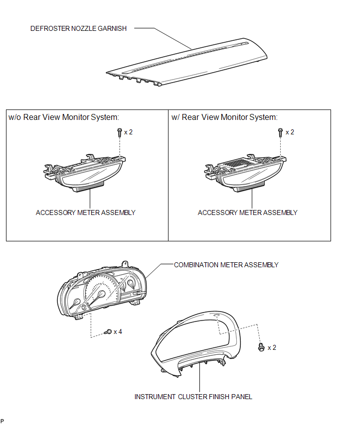
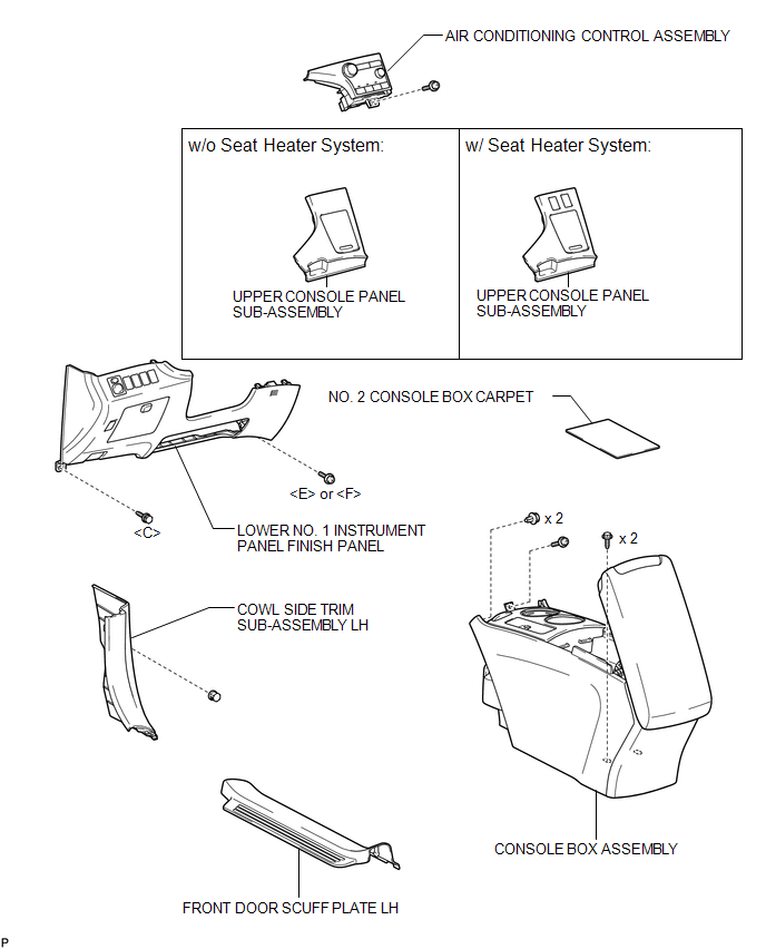
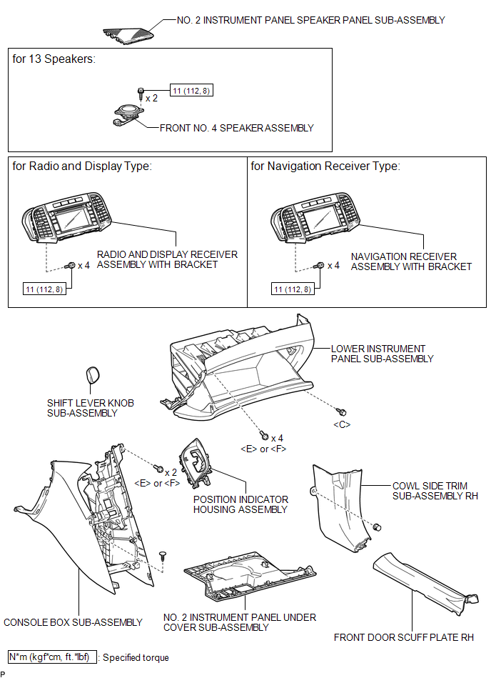
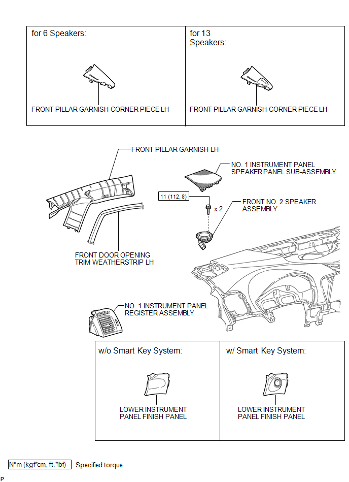
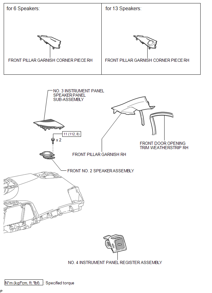
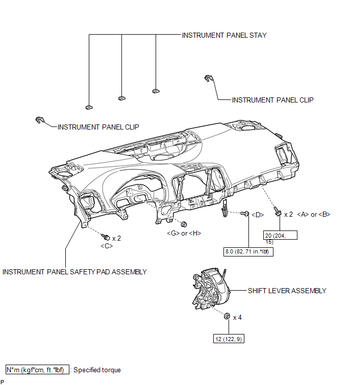
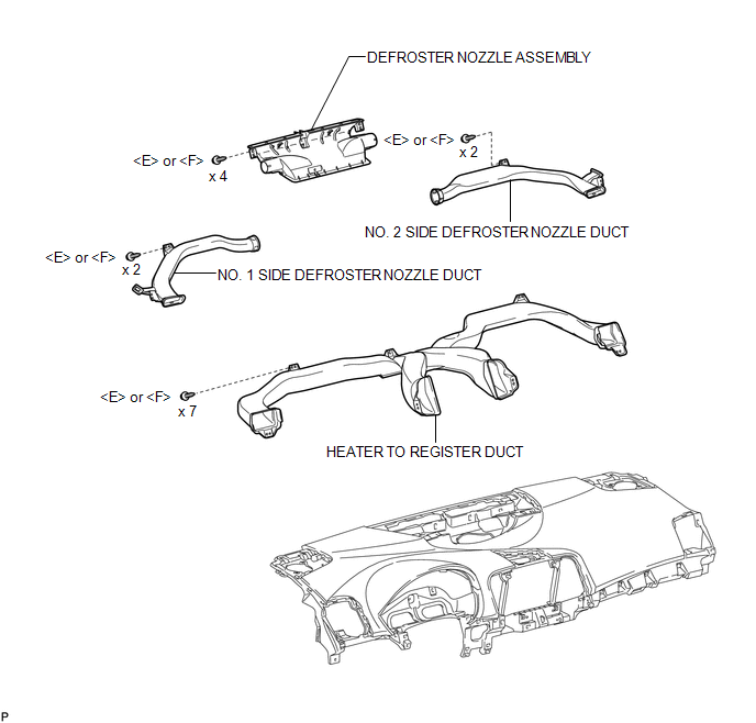
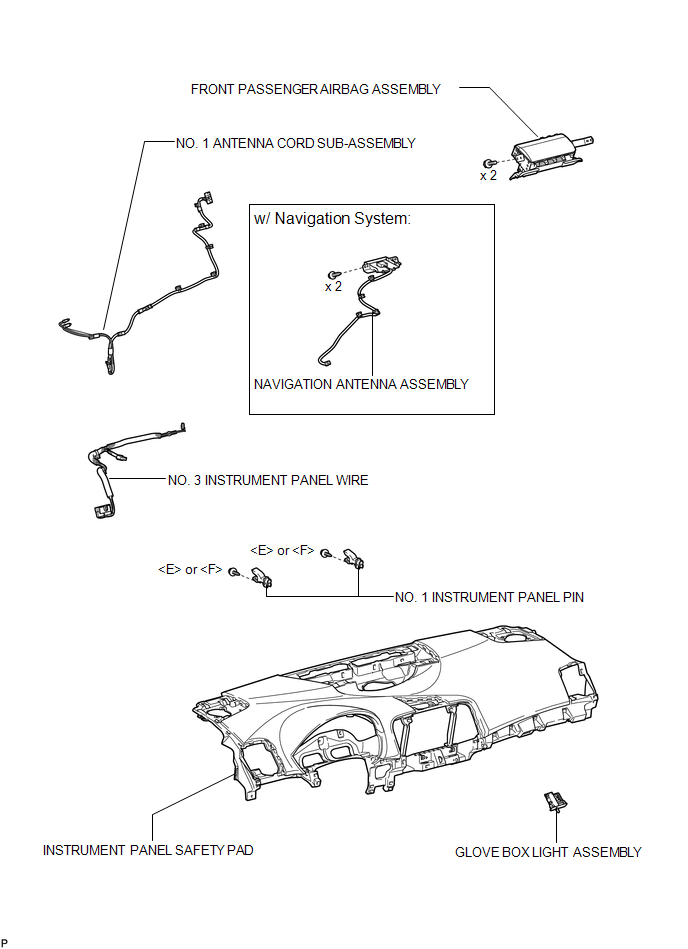
COMPONENTS
ILLUSTRATION
.png)
ILLUSTRATION
.png)
ILLUSTRATION
ILLUSTRATION
ILLUSTRATION
ILLUSTRATION
ILLUSTRATION
ILLUSTRATION
ILLUSTRATION
ILLUSTRATION
 Precaution
PRECAUTION
1. PRECAUTION FOR VEHICLE WITH SRS AIRBAG AND SEAT BELT PRETENSIONER
(a) Some operations in this section may affect the SRS airbags. Prior to performing
the corresponding operations, re ...
 Removal
REMOVAL
PROCEDURE
1. PRECAUTION
(See page )
2. ALIGN FRONT WHEELS FACING STRAIGHT AHEAD
3. DISCONNECT CABLE FROM NEGATIVE BATTERY TERMINAL
CAUTION:
Wait at least 90 seconds after disconnecting ...
Other materials about Toyota Venza:
Inspection
INSPECTION
PROCEDURE
1. INSPECT FRONT LOWER BALL JOINT
(a) Inspect the turning torque of the ball joint.
(1) Secure the front lower ball joint in a vise using aluminum plates.
(2) Install the nut to the front lower ball joint stud.
(3) U ...
Customize Parameters
CUSTOMIZE PARAMETERS
1. CUSTOMIZING FUNCTION WITH TECHSTREAM
HINT:
The items in the table below can be customized.
NOTICE:
When the customer requests a change in a function, first make sure that
the function can be customized.
Be sure to m ...
Rear Occupant Classification Sensor LH Circuit Malfunction (B1782)
DESCRIPTION
The rear occupant classification sensor LH circuit consists of the occupant classification
ECU and rear occupant classification sensor LH.
DTC B1782 is recorded when a malfunction is detected in the rear occupant classification
sensor LH circ ...

0.1723