Toyota Venza: Transfer Case Rear Oil Seal
Components
COMPONENTS
ILLUSTRATION
ILLUSTRATION
Replacement
REPLACEMENT
PROCEDURE
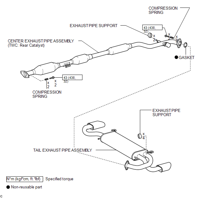
1. REMOVE TAIL EXHAUST PIPE ASSEMBLY
.gif)
2. REMOVE CENTER EXHAUST PIPE ASSEMBLY
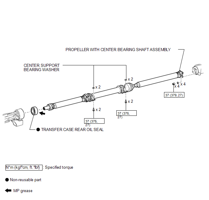
3. REMOVE PROPELLER WITH CENTER BEARING SHAFT ASSEMBLY
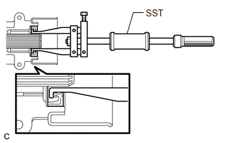
4. REMOVE TRANSFER CASE REAR OIL SEAL
|
(a) Using SST, remove the transfer case rear oil seal from the transfer extension housing sub-assembly. SST: 09308-00010 NOTICE: Be careful not to damage the oil seal contact surface or the inside surface of the oil seal. |
|
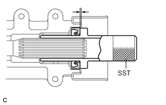
5. INSTALL TRANSFER CASE REAR OIL SEAL
|
(a) Using SST and a hammer, drive in a new transfer case rear oil seal into the transfer extension housing sub-assembly until it reaches the position shown in the illustration. SST: 09325-20010 Drive in depth: 1.1 to 1.9 mm (0.0433 to 0.0748 in.) NOTICE: Do not tilt the oil seal during installation. |
|
(b) Apply a small amount of MP grease to the lip of the oil seal.
6. TEMPORARILY TIGHTEN PROPELLER WITH CENTER BEARING SHAFT ASSEMBLY
7. FULLY TIGHTEN PROPELLER WITH CENTER BEARING SHAFT ASSEMBLY
8. INSTALL CENTER EXHAUST PIPE ASSEMBLY
9. INSTALL TAIL EXHAUST PIPE ASSEMBLY
10. INSPECT TRANSFER OIL
11. INSPECT EXHAUST GAS LEAK
 Transfer Case Front Oil Seal(for Rh Side)
Components
COMPONENTS
ILLUSTRATION
Replacement
REPLACEMENT
PROCEDURE
1. DRAIN TRANSFER OIL
(a) Remove the transfer drain plug and gasket to drain the transfer oil.
(b) Install a new gask ...
 Transfer Oil
On-vehicle Inspection
ON-VEHICLE INSPECTION
PROCEDURE
1. INSPECT TRANSFER OIL
(a) Remove the No. 1 transfer case plug and gasket.
...
Other materials about Toyota Venza:
Clock Display Circuit
DESCRIPTION
The accessory meter assembly uses this circuit to communicate with the combination
meter assembly via the direct line. The accessory meter assembly uses this circuit
to receive the drive monitor switch signals from the combination meter assemb ...
Installation
INSTALLATION
PROCEDURE
1. INSTALL FUEL LID LOCK CONTROL CABLE SUB-ASSEMBLY
(a) Engage the 8 clamps.
(b) Engage the 2 claws and connect the fuel lid lock control cable sub-assembly.
2. INSTALL FUE ...
System Voltage (P0560)
DESCRIPTION
The battery supplies electricity to the ECM even when the ignition switch is
off. This power allows the ECM to store data such as DTC history, freeze frame data
and fuel trim values. If the battery voltage falls below a minimum level, the stor ...

0.1456