Toyota Venza: Transfer Case Front Oil Seal(for Rh Side)
Components
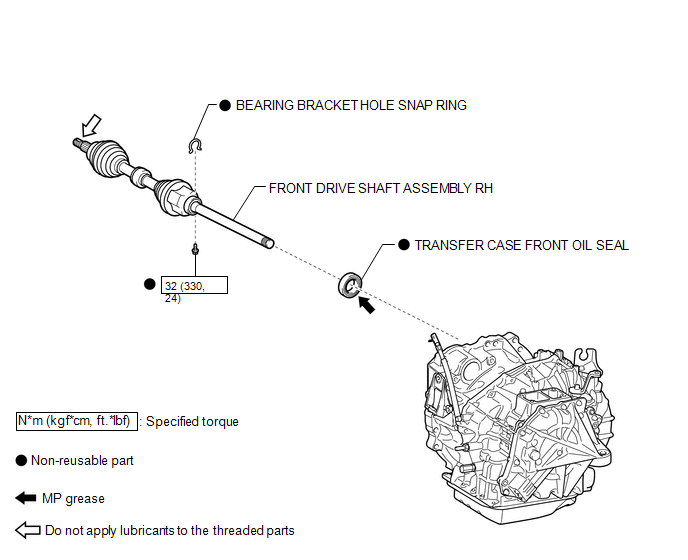
COMPONENTS
ILLUSTRATION
Replacement
REPLACEMENT
PROCEDURE
1. DRAIN TRANSFER OIL
(a) Remove the transfer drain plug and gasket to drain the transfer oil.
(b) Install a new gasket and the transfer drain plug.
Torque:
49 N·m {500 kgf·cm, 36 ft·lbf}
2. REMOVE FRONT DRIVE SHAFT ASSEMBLY RH
(See page .gif) ).
).
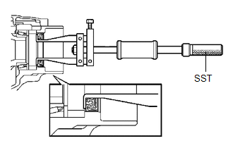
3. REMOVE TRANSFER CASE FRONT OIL SEAL
|
(a) Using SST, remove the transfer case front oil seal from the transfer case. SST: 09308-00010 NOTICE: Do not damage the oil seal contact surface on the case. |
|
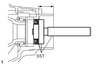
4. INSTALL TRANSFER CASE FRONT OIL SEAL
|
(a) Using SST, drive in a new transfer case front oil seal into the transfer case until it reaches the position shown in the illustration. SST: 09950-60010 09951-00350 09951-00580 09952-06010 SST: 09950-70010 09951-07150 Drive in depth: 33.5 to 34.5 mm (1.319 to 1.358 in.) NOTICE: Do not tilt the oil seal during installation. |
|
(b) Apply a small amount of MP grease to the lip of the oil seal.
5. INSTALL FRONT DRIVE SHAFT ASSEMBLY RH
(See page ).
6. ADD TRANSFER OIL
7. INSPECT TRANSFER OIL
 Transfer Case Front Oil Seal(when Using The Engine Support Bridge)
Components
COMPONENTS
ILLUSTRATION
Replacement
REPLACEMENT
PROCEDURE
1. REMOVE TRANSFER ASSEMBLY
See page
2. REMOVE TRANSFER CASE FRONT OIL SEAL
(a) Using SST, remove the t ...
 Transfer Case Rear Oil Seal
Components
COMPONENTS
ILLUSTRATION
ILLUSTRATION
Replacement
REPLACEMENT
PROCEDURE
1. REMOVE TAIL EXHAUST PIPE ASSEMBLY
2. REMOVE CENTER EXHAUST PIPE ASSEMBLY
3. REMOVE PROPELLER ...
Other materials about Toyota Venza:
Crankshaft Position - Camshaft Position Correlation (Bank 1 Sensor A) (P0016,P0017)
DESCRIPTION
In the VVT (Variable Valve Timing) system, the appropriate intake and exhaust
valve open and close timing is controlled by the ECM. The ECM performs intake and
exhaust valve control by performing the following: 1) controlling the camshaft and ...
Portable Player cannot be Registered
CAUTION / NOTICE / HINT
HINT:
Some versions of "Bluetooth" compatible audio players may not function properly,
or the functions may be limited using the radio and display receiver assembly, even
if the portable audio player itself can play file ...
Wireless-linked Return Function does not Operate
DESCRIPTION
When the vehicle doors are unlocked through wireless unlock or entry unlock*1
operation, the certification ECU (smart key ECU assembly)*1 or main body ECU (driver
side junction block assembly) sends the key ID signal and memory call request si ...

0.1691