Toyota Venza: Removal
REMOVAL
CAUTION / NOTICE / HINT
CAUTION:
- Wear protective gloves when removing the exhaust pipe.
- The exhaust pipe is extremely hot immediately after the engine has stopped.
- Confirm that the exhaust pipe has cooled down before removing it.
PROCEDURE
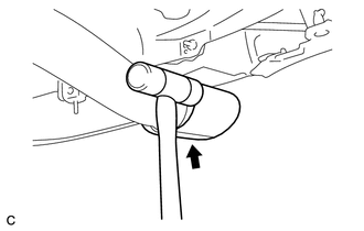
1. REMOVE TAIL EXHAUST PIPE BAFFLE SUB-ASSEMBLY
|
(a) Using a plastic hammer, uniformly tap off the tail exhaust pipe baffle sub-assembly. |
|
2. REMOVE TAIL EXHAUST PIPE ASSEMBLY
|
(a) Remove the 2 bolts and 2 compression springs. |
|
.png)
(b) Disconnect the tail exhaust pipe assembly from the 4 exhaust pipe supports.
(c) Remove the gasket from the center exhaust pipe assembly.
3. REMOVE CENTER EXHAUST PIPE ASSEMBLY
|
(a) Remove the 2 bolts. |
|
.png)
(b) Disconnect the center exhaust pipe assembly from the 2 exhaust pipe supports.
(c) Remove the gasket from the center exhaust pipe assembly.
4. REMOVE FRONT EXHAUST PIPE ASSEMBLY
|
(a) Disconnect the heated oxygen sensor connector. |
|
.png)
|
(b) Remove the 2 bolts, 2 compression springs and front exhaust pipe assembly from the exhaust manifold converter sub-assembly. |
|
.png)
(c) Remove the gasket from the exhaust manifold converter sub-assembly.
5. REMOVE HEATED OXYGEN SENSOR
.gif)
 Installation
INSTALLATION
PROCEDURE
1. INSTALL HEATED OXYGEN SENSOR
2. INSTALL FRONT EXHAUST PIPE ASSEMBLY
(a) Using a vernier caliper, measure the free length of the compression
springs.
...
 Intake Air Control Valve Actuator(for Tcv)
Components
COMPONENTS
ILLUSTRATION
Removal
REMOVAL
PROCEDURE
1. REMOVE INTAKE MANIFOLD
(a) Remove the intake manifold (See page ).
2. REMOVE INTAKE AIR CONTROL VALVE ACTUATOR (for TCV)
...
Other materials about Toyota Venza:
USB Media Malfunction (B1585)
DESCRIPTION
This DTC is stored when a malfunction occurs in a connected device.
DTC No.
DTC Detection Condition
Trouble Area
B1585
When any of the following conditions is met:
A non m ...
Bank 1 Air-Fuel Ratio Imbalance (P219A,P219C-P219F)
DESCRIPTION
Refer to DTC P0300 (See page ).
Refer to DTC P2195 (See page ).
DTC No.
DTC Detection Condition
Trouble Area
P219A
The difference in air fuel ratios between the cylinders exceeds the ...
On-vehicle Inspection
ON-VEHICLE INSPECTION
PROCEDURE
1. INSPECT COOLING FAN MOTOR
(a) Check that the motor operates smoothly when the battery is connected
to the cooling fan motor connector.
Text in Illustration
*1
Componen ...

0.1224