Toyota Venza: Sound Signal Circuit between Radio Receiver and Stereo Jack Adapter
DESCRIPTION
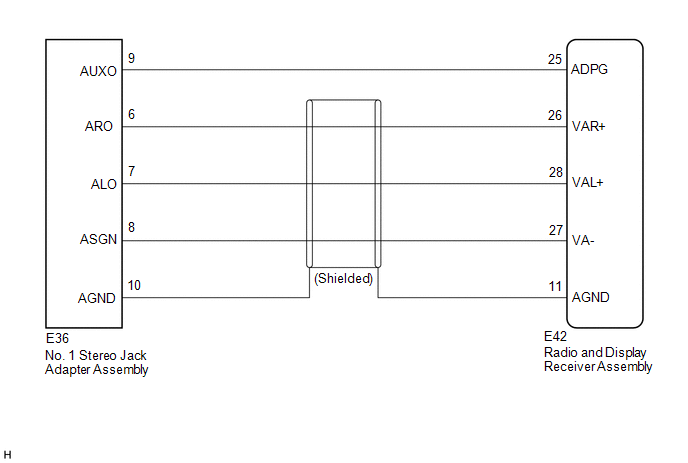
- The No. 1 stereo jack adapter assembly sends the sound signal from an
external device to the radio and display receiver assembly via this circuit.
The sound signal that has been sent is amplified by the radio and display receiver assembly and then is sent to the speakers.
If there is an open or short in the circuit, sound cannot be heard from the speakers even if there is no malfunction in the radio and display receiver assembly or speakers.
WIRING DIAGRAM
PROCEDURE
|
1. |
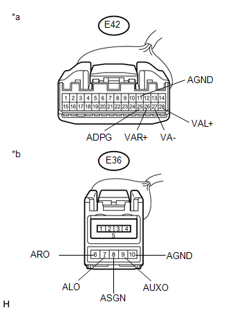
CHECK HARNESS AND CONNECTOR (RADIO AND DISPLAY RECEIVER ASSEMBLY - NO. 1 STEREO JACK ADAPTER ASSEMBLY) |
(a) Disconnect the E42 radio and display receiver assembly connector.
(b) Disconnect the E36 No. 1 stereo jack adapter assembly connector.
|
(c) Measure the resistance according to the value(s) in the table below. Standard Resistance:
|
|
| OK | .gif) |
PROCEED TO NEXT SUSPECTED AREA SHOWN IN PROBLEM SYMPTOMS TABLE |
| NG | |
REPAIR OR REPLACE HARNESS OR CONNECTOR |
 Speaker Circuit
DESCRIPTION
If there is a short in a speaker circuit, the radio and display receiver
assembly detects it and stops output to the speakers.
Thus sound cannot be heard from the speakers ...
 Data Signal Circuit between Radio Receiver and Stereo Jack Adapter
DESCRIPTION
The No. 1 stereo jack adapter assembly sends the sound data signal or image data
signal from a USB device to the radio and display receiver assembly via this circuit.
WIRING DIAGRAM
...
Other materials about Toyota Venza:
Rear Occupant Classification Sensor LH Collision Detection (B1787)
DESCRIPTION
DTC B1787 is output when the occupant classification ECU receives a collision
detection signal sent by the rear occupant classification sensor LH if an accident
occurs.
DTC B1787 is also output when the front seat assembly RH is subjected to ...
Removal
REMOVAL
CAUTION / NOTICE / HINT
HINT:
Use the same procedure for the LH side and RH side.
The following procedure is for the LH side.
If the sensor rotor needs to be replaced, replace it together with the
rear drive shaft assembly.
...
Transfer Case Front Oil Seal(when Using The Engine Support Bridge)
Components
COMPONENTS
ILLUSTRATION
Replacement
REPLACEMENT
PROCEDURE
1. REMOVE TRANSFER ASSEMBLY
See page
2. REMOVE TRANSFER CASE FRONT OIL SEAL
(a) Using SST, remove the transfer case front oil seal from the transfer
case.
S ...

0.1344