Toyota Venza: Tongue Plate Stopper
Components
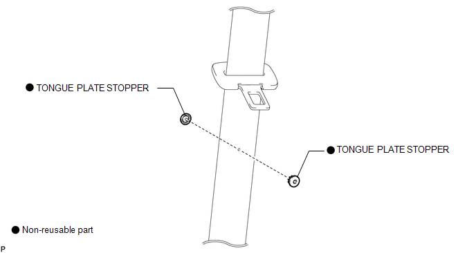
COMPONENTS
ILLUSTRATION
Replacement
REPLACEMENT
PROCEDURE
1. REMOVE TONGUE PLATE STOPPER
|
(a) Slide the tongue plate above the installation position of the tongue plate stopper, and temporarily hold it with adhesive tape. |
|
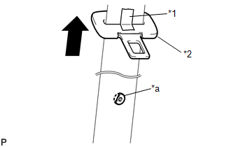
(b) Remove any pieces of the original tongue plate stopper in the belt webbing with a pair of pliers.
NOTICE:
Be careful not to damage the belt webbing during repair.
Text in Illustration|
*1 |
Adhesive Tape |
|
*2 |
Tongue Plate |
|
*a |
Broken Tongue Plate Stopper |
2. INSTALL TONGUE PLATE STOPPER
|
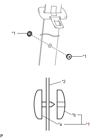
(a) Position a new tongue plate stopper in the hole of the belt webbing. Text in Illustration
HINT: Make sure that the installation direction of the tongue plate stopper is as shown in the illustration. |
|
|
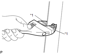
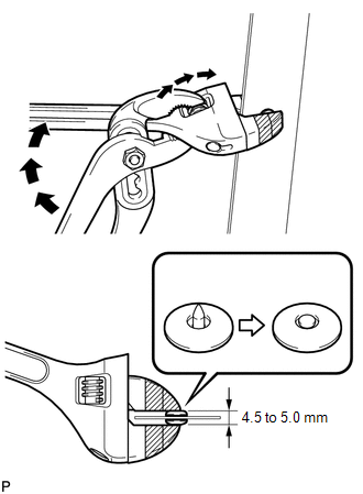
(b) Hold the tongue plate stopper in the hole of the belt webbing using an adjustable wrench, and turn the adjustment screw of the adjustable wrench by hand to compress the tongue plate stopper. Text in Illustration
NOTICE:
HINT: Tape the jaws of the adjustable wrench before use. |
|
|
(c) When the adjustment screw of the adjustable wrench cannot be turned by hand, tighten the adjustment screw using a pair of adjustable joint pliers until the tongue plate stopper thickness is 4.5 to 5.0 mm (0.177 to 0.197 in.). (Refer to the illustrations.) |
|
|
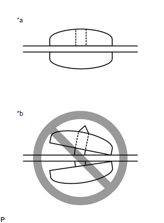
(d) Make sure that the male pin of the tongue plate stopper has expanded evenly in the hole of the female part and is firmly held to the belt webbing. (Refer to the illustrations.) Text in Illustration
|
|
 Front Passenger Side Seat Belt Warning Light Malfunction
DESCRIPTION
The occupant classification ECU detects the state of the front seat inner belt
assembly RH and load sensor when the front passenger side seat is occupied with
the ignition switch ON. ...

Other materials about Toyota Venza:
Disassembly
DISASSEMBLY
PROCEDURE
1. INSPECT CONNECTING ROD THRUST CLEARANCE
(a) Using a dial indicator, measure the thrust clearance while moving
the connecting rod back and forth.
Standard thrust clearance:
0.160 to 0.512 mm (0.00630 to 0.0202 i ...
Removal
REMOVAL
PROCEDURE
1. DISCONNECT CABLE FROM NEGATIVE BATTERY TERMINAL
NOTICE:
When disconnecting the cable, some systems need to be initialized after the cable
is reconnected (See page ).
2. REMOVE UPPER CONSOLE PANEL SUB-ASSEMBLY (w/o Seat Heater Syste ...
Brake Override System
DESCRIPTION
When the vehicle is being driven, depressing the accelerator pedal sensor assembly
and brake pedal will activate the brake override system to restrict driving torque.
The conditions for activating the brake override system as well as the items ...

0.1569