Toyota Venza: Removal
REMOVAL
PROCEDURE
1. REMOVE BACK DOOR PANEL TRIM ASSEMBLY
.gif)
2. REMOVE REAR WIPER ARM HEAD CAP
3. REMOVE REAR WIPER ARM AND BLADE ASSEMBLY
4. REMOVE REAR WIPER MOTOR GROMMET
5. REMOVE REAR WIPER MOTOR AND BRACKET ASSEMBLY
6. REMOVE REAR LIGHT ASSEMBLY LH
7. REMOVE REAR LIGHT ASSEMBLY RH
HINT:
Use the same procedure for the RH side and LH side.
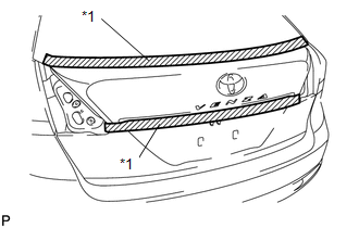
8. REMOVE BACK DOOR OUTSIDE GARNISH SUB-ASSEMBLY
|
(a) Put protective tape around the back door outside garnish sub-assembly. Text in Illustration
|
|
(b) Disconnect each connector.
|
(c) Remove the 5 nuts. |
|
.png)
|
(d) Disengage the 16 clips and remove the back door outside garnish sub-assembly. |
|
.png)
(e) Remove the 16 clips (back door moulding clip) from the back door outside garnish sub-assembly.
(f) Remove the 5 gaskets and 5 stud bolts from the back door outside garnish sub-assembly.
9. REMOVE NO. 1 BACK DOOR EMBLEM
10. REMOVE NO. 2 BACK DOOR NAME PLATE
11. REMOVE BACK DOOR OPENER SWITCH ASSEMBLY
12. REMOVE TELEVISION CAMERA ASSEMBLY (w/ Rear View Monitor System)
 Installation
INSTALLATION
PROCEDURE
1. INSTALL TELEVISION CAMERA ASSEMBLY (w/ Rear View Monitor System)
2. INSTALL BACK DOOR OPENER SWITCH ASSEMBLY
3. INSTALL NO. 1 BACK DOOR EMBLEM
4. INSTALL NO. 2 ...

Other materials about Toyota Venza:
Opening the fuel tank cap
Perform the following steps to open the fuel tank cap.
- Before refueling the vehicle
• Vehicles with smart key system
Turn the “ENGINE START STOP” switch off and ensure that all the doors and windows
are closed.
• Vehicles without smart ke ...
Air conditioning filter
The air conditioning filter must be changed regularly to maintain air conditioning
efficiency.
- Removal method
Vehicles with smart key system:
Turn the “ENGINE START STOP” switch off.
Vehicles without smart key system:
Turn the engine switch ...
Installation
INSTALLATION
PROCEDURE
1. INSTALL FRONT DOOR LOCK ASSEMBLY
NOTICE:
When reusing the removed front door lock assembly, replace the door
lock wiring harness seal on the connector with a new one.
Do not allow grease or dust to adhere to the do ...

0.132