Toyota Venza: Front Passenger Side Seat Belt Warning Light Malfunction
DESCRIPTION
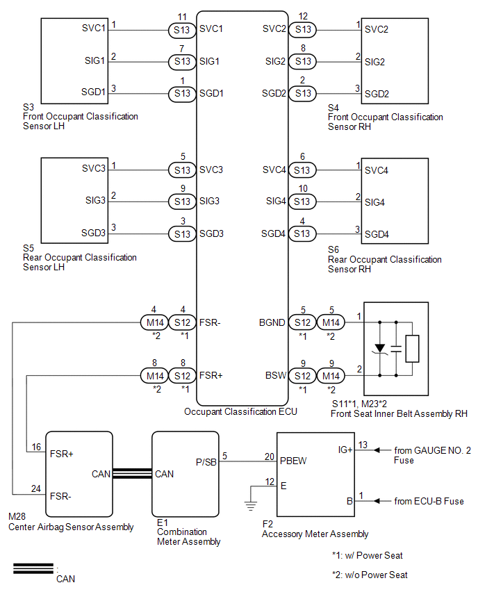
The occupant classification ECU detects the state of the front seat inner belt assembly RH and load sensor when the front passenger side seat is occupied with the ignition switch ON. If the front passenger side seat belt is not fastened, the front passenger side seat belt warning light on the accessory meter assembly blinks. If the seat belt is fastened, the warning light goes off.
WIRING DIAGRAM
CAUTION / NOTICE / HINT
NOTICE:
- Inspect the fuses for circuits related to this system before performing the following inspection procedure.
- The seat belt warning system uses the CAN communication system. First,
confirm that there is no malfunction in the CAN communication system. Refer
to the How to Proceed with Troubleshooting procedure (See page
.gif) ).
).
PROCEDURE
|
1. |
CHECK DTC OUTPUT (CAN COMMUNICATION SYSTEM) |
(a) Clear the DTC (See page ).
(b) Recheck for DTCs.
|
Result |
Proceed to |
|---|---|
|
DTC is not output |
A |
|
DTC is output |
B |
| B | .gif) |
GO TO CAN COMMUNICATION SYSTEM |
|
.gif)
|
2. |
CHECK DTC OUTPUT (OCCUPANT CLASSIFICATION SYSTEM) |
(a) Clear the DTC (See page ).
(b) Recheck for DTCs.
|
Result |
Proceed to |
|---|---|
|
DTC is not output |
A |
|
DTC is output |
B |
| B | |
GO TO OCCUPANT CLASSIFICATION SYSTEM |
|
|
3. |
CHECK DTC OUTPUT (AIRBAG SYSTEM) |
(a) Clear the DTC (See page ).
(b) Recheck for DTCs.
|
Result |
Proceed to |
|---|---|
|
DTC is not output |
A |
|
DTC is output |
B |
| B | |
GO TO AIRBAG SYSTEM |
|
|
4. |
PERFORM ACTIVE TEST USING TECHSTREAM |
(a) Connect the Techstream to the DLC3.
(b) Turn the ignition switch to ON.
(c) Turn the Techstream on.
(d) Enter the following menus: Body Electrical / Combination Meter / Active Test.
(e) Perform the Active Test according to the display on the Techstream.
Combination Meter (Combination Meter Assembly)|
Tester Display |
Test Part |
Control Range |
Diagnostic Note |
|---|---|---|---|
|
Front Passenger Side Seat Belt |
Front passenger side seat belt warning light |
OFF or ON |
Confirm that the vehicle stopped with the engine idling |
OK:
The front passenger side seat belt warning light on the accessory meter assembly operates normally.
| OK | |
REPLACE COMBINATION METER ASSEMBLY |
|
|
5. |
CHECK HARNESS AND CONNECTOR (BATTERY AND BODY GROUND) |
|
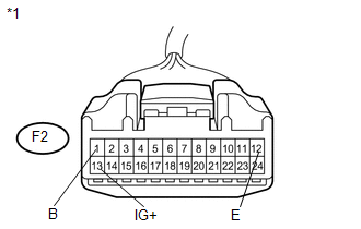
(a) Disconnect the F2 connector. |
|
(b) Measure the voltage and resistance according to the value(s) in the table below.
Standard Voltage:
|
Tester Connection |
Condition |
Specified Condition |
|---|---|---|
|
F2-1 (B) - Body ground |
Always |
11 to 14 V |
|
F2-13 (IG+) - Body ground |
Ignition switch ON |
11 to 14 V |
|
F2-13 (IG+) - Body ground |
Ignition switch off |
Below 1 V |
Standard Resistance:
|
Tester Connection |
Condition |
Specified Condition |
|---|---|---|
|
F2-12 (E) - Body ground |
Always |
Below 1 Ω |
|
*1 |
Front view of wire harness connector (to Accessory Meter Assembly) |
| NG | |
REPAIR OR REPLACE HARNESS OR CONNECTOR |
|
|
6. |
CHECK HARNESS AND CONNECTOR (COMBINATION METER - ACCESSORY METER) |
|
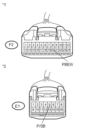
(a) Disconnect the E1 connector. |
|
(b) Measure the resistance according to the value(s) in the table below.
Standard Resistance:
|
Tester Connection |
Condition |
Specified Condition |
|---|---|---|
|
E1-5 (P/SB) - F2-20 (PBEW) |
Always |
Below 1 Ω |
|
F2-20 (PBEW) - Body ground |
Always |
10 kΩ or higher |
|
*1 |
Front view of wire harness connector (to Accessory Meter Assembly) |
|
*2 |
Front view of wire harness connector (to Combination Meter Assembly) |
| NG | |
REPAIR OR REPLACE HARNESS OR CONNECTOR |
|
|
7. |
REPLACE ACCESSORY METER ASSEMBLY |
(a) Replace the accessory meter assembly (See page
).
|
|
8. |
CHECK FRONT PASSENGER SIDE SEAT BELT WARNING LIGHT |
(a) Check the front passenger side seat belt warning light operation (See page
).
| OK | |
END (ACCESSORY METER ASSEMBLY WAS DEFECTIVE) |
| NG | |
REPLACE COMBINATION METER ASSEMBLY |
 On-vehicle Inspection
ON-VEHICLE INSPECTION
PROCEDURE
1. INSPECT DRIVER SIDE SEAT BELT WARNING
(a) Turn the ignition switch to ON.
(b) When the driver side seat belt is not fastened, check that the driver side
seat b ...
 Tongue Plate Stopper
Components
COMPONENTS
ILLUSTRATION
Replacement
REPLACEMENT
PROCEDURE
1. REMOVE TONGUE PLATE STOPPER
(a) Slide the tongue plate above the installation position of the tongue
...
Other materials about Toyota Venza:
Test Mode Procedure
TEST MODE PROCEDURE
1. ENTER TEST MODE (SIGNAL CHECK MODE)
(a) Turn the ignition switch off.
(b) Connect the Techstream to the DLC3.
(c) Turn the ignition switch to ON.
(d) Check that the tire pressure warning light comes on for 3 seconds and then
goes ...
Removal
REMOVAL
PROCEDURE
1. REMOVE FRONT SEAT HEADREST ASSEMBLY
2. REMOVE FRONT SEAT REAR OUTER TRACK COVER
3. REMOVE FRONT SEAT REAR INNER TRACK COVER
4. REMOVE FRONT SEAT ASSEMBLY
5. REMOVE RECLINING POWER SEAT SWITCH KNOB
6. REMOVE SLIDE AND VER ...
Installation
INSTALLATION
PROCEDURE
1. INSTALL STEERING INTERMEDIATE SHAFT ASSEMBLY
(a) Align the matchmarks on the steering intermediate shaft assembly
and the steering column assembly.
Text in Illustration
*1
Matc ...

0.1349