Toyota Venza: Tire section names
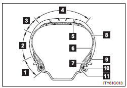
1. Bead
2. Sidewall
3. Shoulder
4. Tread
5. Belt
6. Inner liner
7. Reinforcing rubber
8. Carcass
9. Rim lines
10. Bead wires
11. Chafer
 Tire size
- Typical tire size information
The illustration indicates typical tire size.
1. Tire use
(P = Passenger car, T = Temporary use)
2. Section width (millimeters)
3. Aspect ratio
(tire heig ...
 Uniform Tire Quality Grading
This information has been prepared in accordance with regulations issued by the
National Highway Traffic Safety Administration of the U.S. Department of Transportation.
It provides the purchasers a ...
Other materials about Toyota Venza:
Lost Communication with ECM / PCM "A" (U0100)
DESCRIPTION
The power management control ECU receives shift position information from 2 sources.
It receives a shift position P signal from the shift lock control unit assembly
via a direct line, and shift position information from the ECM via CAN. If the ...
Body
General Maintenance
GENERAL MAINTENANCE
PROCEDURE
1. TIGHTEN BOLTS AND NUTS ON CHASSIS AND BODY
(a) If necessary, tighten the bolts and nuts on the chassis parts listed below.
Front axle and suspension
Drivetrain
Rear axle and suspension ...
Removal
REMOVAL
PROCEDURE
1. PRECAUTION
(See page )
NOTICE:
After turning the ignition switch off, waiting time may be required before disconnecting
the cable from the negative (-) battery terminal. Therefore, make sure to read the
disconnecting the cable fr ...

0.1139