Toyota Venza: Emission Control System
Parts Location
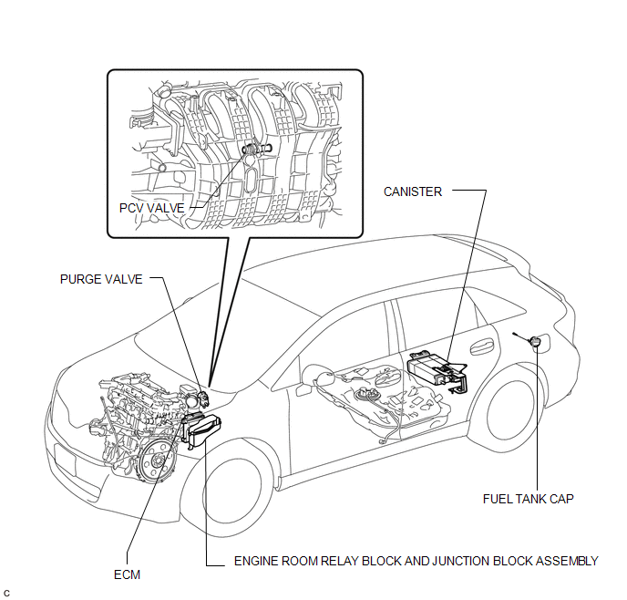
PARTS LOCATION
ILLUSTRATION
On-vehicle Inspection
ON-VEHICLE INSPECTION
PROCEDURE
1. INSPECT FUEL CUT-OFF RPM
(a) Increase the engine speed to at least 3500 rpm.
|
(b) Use a sound scope to check for injector operating sounds. Text in Illustration
|
|
(c) When the accelerator pedal is released, check that injector operating sounds stop momentarily and then resume.
Standard:
|
Item |
Specified Condition |
|---|---|
|
Fuel injection restart rpm |
1400 rpm |
If the result is not as specified, check the injectors, wiring and ECM.
2. VISUALLY INSPECT HOSES, CONNECTIONS AND GASKETS
(a) Inspect the hoses and gaskets for scratches, cracks or air/oil leaks from the connecting parts.
HINT:
If the hoses or gaskets are damaged or some of the connections are loose, they may cause an engine stall or malfunction.
3. INSPECT EVAPORATIVE EMISSION CONTROL SYSTEM
(a) Connect the Techstream to the DLC3.
|
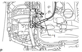
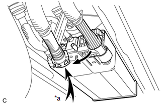
(b) Disconnect the fuel vapor feed hose from the purge VSV shown in the illustration. |
|
(c) Start the engine.
(d) Enter the following menus: Powertrain / Engine and ECT / Active Test / Activate the VSV for Evap Control.
(e) Check that vacuum occurs at the purge VSV port.
(f) If vacuum does not occur, check the following items.
- Purge VSV (for canister purge)
- Clogging in the fuel vapor feed hose connecting the intake manifold and purge VSV
- Voltage from the ECM PRG terminal (See page
.gif) )
)
(g) Exit Active Test mode and reconnect the fuel vapor feed hose.
(h) Enter the following menus: Powertrain / Engine and ECT / Data List / EVAP Purge VSV.
(i) Warm up the engine and drive the vehicle.
(j) Confirm that the purge VSV opens.
If the result is not as specified, replace the purge VSV, wire harness or ECM.
4. CHECK FUEL TANK AND VENT LINE
(a) Disconnect the vent line tube from the charcoal canister sub-assembly.
(b) Connect a pressure gauge to the vent line tube.
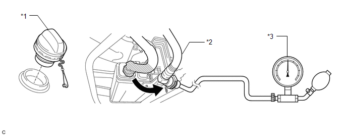 Text in Illustration
|
*1 |
Fuel Tank Cap |
*2 |
Vent Line Tube |
|
*3 |
Pressure Gauge |
- |
- |
(c) Apply 4 kPa (0.04 kgf/cm2, 0.6 psi) of pressure to the vent line of the fuel tank.
HINT:
Perform this inspection with the fuel tank less than 90% full. When the fuel tank is full, the fuel fill check valve closes and the pressure is released through the 2 mm orifice. As a result, when the fuel tank cap is removed, the pressure does not decrease smoothly.
(d) Check that the fuel tank pressure is maintained for some time, and does not decrease immediately.
HINT:
If the pressure decreases immediately, one of the following may apply:
- The fuel tank cap is not completely tightened.
- The fuel tank cap is damaged.
- Air is leaking from the vent line.
- The fuel tank is damaged.
(e) When the fuel tank cap is removed, check that the pressure is released smoothly.
HINT:
If the pressure does not drop, replace the fuel tank assembly.
(f) Reconnect the vent line tube to the charcoal canister sub-assembly.
5. INSPECT AIR INLET LINE
|
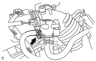
(a) Disconnect the air line tube from the charcoal canister sub-assembly. Text in Illustration
|
|
(b) Check that air flows freely into the air line.
If air does not flow freely into the air line, repair or replace the air line tube.
(c) Reconnect the air line tube to the charcoal canister sub-assembly.
System Diagram
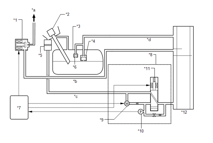
SYSTEM DIAGRAM
 Text in Illustration
|
*1 |
Purge VSV |
*2 |
Fuel Tank Cap |
|
*3 |
Fuel Tank |
*4 |
Fuel Fill Check Valve |
|
*5 |
Canister Filter |
*6 |
Fuel Cut-off Valve |
|
*7 |
ECM |
*8 |
Canister Pump Module |
|
*9 |
Pump Motor |
*10 |
Canister Pressure Sensor |
|
*11 |
Vent Valve |
*12 |
Charcoal Canister |
|
*a |
to Intake Manifold |
*b |
Purge Line |
|
*c |
Air Line |
*d |
Vent Line |
 Installation
INSTALLATION
PROCEDURE
1. INSTALL CHARCOAL CANISTER LEAK DETECTION PUMP SUB-ASSEMBLY
(a) Engage the 2 claws to install a new charcoal canister leak detection
pump sub-assembly to the ...
 Fuel Tank Cap
Inspection
INSPECTION
PROCEDURE
1. INSPECT FUEL TANK CAP ASSEMBLY
(a) Visually check that the fuel tank cap assembly and gasket are not
deformed or damaged.
Text in Illustratio ...
Other materials about Toyota Venza:
Voice Guidance does not Function
PROCEDURE
1.
CHECK VOICE GUIDANCE
(a) Check that the voice guidance settings are not off.
OK:
Voice guidance settings are not off.
NG
CHANGE THE VOICE GUIDANCE SETTINGS TO ON
...
Problem Symptoms Table
PROBLEM SYMPTOMS TABLE
HINT:
Use the table below to help determine the cause of problem symptoms. If multiple
suspected areas are listed, the potential causes of the symptoms are listed in order
of probability in the "Suspected Area" column of ...
Installation
INSTALLATION
PROCEDURE
1. INSTALL WINDSHIELD WIPER MOTOR ASSEMBLY
(a) Using a T30 "TORX" socket wrench, install the windshield wiper motor
assembly with the 2 bolts.
Torque:
7.5 N·m {76 kgf·cm, 66 in·lbf}
...

0.1168