Toyota Venza: Tire Pressure Warning Light Circuit
DESCRIPTION
If the tire pressure warning ECU detects a malfunction, the tire pressure warning light blinks for 1 minute then stays on and tire pressure monitor is canceled at the same time. At this time, the ECU records a DTC in the memory.
Connecting terminals TC and CG of the DLC3 allows the tire pressure warning light to blink output DTCs.
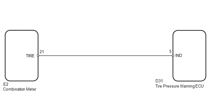
WIRING DIAGRAM
CAUTION / NOTICE / HINT
NOTICE:
- When replacing the tire pressure warning ECU, read the transmitter IDs stored in the old ECU using the Techstream and write them down before removal.
- It is necessary to perform registration (See page
.gif) ) of the transmitter IDs into the tire
) of the transmitter IDs into the tire
pressure warning ECU if the ECU has been replaced.
PROCEDURE
|
1. |
CHECK OPERATION OF TIRE PRESSURE WARNING LIGHT (ACTIVE TEST) |
(a) Turn the ignition switch off.
(b) Connect the Techstream to the DLC3.
(c) Turn the ignition switch to ON.
(d) Turn the Techstream on.
(e) Enter the following menus: Body Electrical / Combination Meter / Active Test.
(f) Check the condition of the tire pressure warning light by operating the Techstream.
Combination Meter|
Tester Display |
Test Part |
Control Range |
Diagnostic Note |
|---|---|---|---|
|
Indicat. Tire Pressure Warning System |
Tire pressure warning light |
Tire pressure warning light is off or on |
Confirm that the vehicle is stopped with the engine idling |
OK:
The warning light turns on when operating the Techstream.
| NG | .gif) |
GO TO METER / GAUGE SYSTEM |
|
.gif)
|
2. |
CHECK HARNESS AND CONNECTOR (COMBINATION METER - TIRE PRESSURE WARNING ECU) |
|
(a) Disconnect the E2 combination meter connector. |
|
(b) Disconnect the D31 tire pressure warning ECU connector.
(c) Measure the resistance according to the value(s) in the table below.
Standard Resistance:
|
Tester Connection |
Condition |
Specified Condition |
|---|---|---|
|
E2-21 (TIRE) - D31-5 (IND) |
Always |
Below 1 Ω |
|
E2-21 (TIRE) - Body ground |
10 kΩ or higher |
|
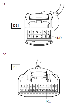
*1 |
Front view of wire harness connector (to Tire Pressure Warning ECU) |
|
*2 |
Front view of wire harness connector (to Combination Meter) |
| OK | |
REPLACE TIRE PRESSURE WARNING ECU |
| NG | |
REPAIR OR REPLACE HARNESS OR CONNECTOR |
 ECU Power Source Circuit
DESCRIPTION
This is the power source for the tire pressure warning ECU.
WIRING DIAGRAM
CAUTION / NOTICE / HINT
NOTICE:
When replacing the tire pressure warning ECU, read the transmitter ...
 TC and CG Terminal Circuit
DESCRIPTION
DTC output mode is set by connecting terminals 13 (TC) and 4 (CG) of the DLC3.
The DTCs are indicated by the blinking pattern of the tire pressure warning light.
WIRING DIAGRAM
HINT ...
Other materials about Toyota Venza:
Removal
REMOVAL
CAUTION / NOTICE / HINT
HINT:
Use the same procedure for the RH side and LH side.
The procedure listed below is for the LH side.
PROCEDURE
1. PRECAUTION
CAUTION:
Be sure to read Precaution thoroughly before servicing (See page
...
Terminals Of Ecu
TERMINALS OF ECU
1. CHECK CERTIFICATION ECU (SMART KEY ECU ASSEMBLY)
(a) Disconnect the D25 certification ECU (smart key ECU assembly) connector.
(b) Measure the voltage and resistance according to the value(s) in the table
below.
HINT:
Measure the va ...
VSC OFF Indicator Light Remains ON
DESCRIPTION
The skid control ECU is connected to the combination meter via CAN communication.
Pressing the VSC OFF switch turns off traction control and pressing and holding
this switch turns off traction and VSC controls. If VSC control is turned off, the ...

0.1568