Toyota Venza: ECU Power Source Circuit
DESCRIPTION
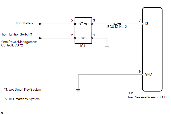
This is the power source for the tire pressure warning ECU.
WIRING DIAGRAM
CAUTION / NOTICE / HINT
NOTICE:
- When replacing the tire pressure warning ECU, read the transmitter IDs stored in the old ECU using the Techstream and write them down before removal.
- It is necessary to perform registration (See page
.gif) ) of the transmitter IDs into the tire
) of the transmitter IDs into the tire
pressure warning ECU after the ECU has been replaced.
PROCEDURE
|
1. |
INSPECT FUSE (ECU-IG NO. 2) |
(a) Remove the ECU-IG No. 2 fuse from the driver side junction block.
(b) Measure the resistance according to the value(s) in the table below.
Standard Resistance:
|
Tester Connection |
Condition |
Specified Condition |
|---|---|---|
|
ECU-IG No. 2 fuse |
Always |
Below 1 Ω |
| NG | .gif) |
REPLACE FUSE |
|
.gif)
|
2. |
INSPECT IGNITION RELAY NO. 1 |
|
(a) Remove the IG1 relay from the driver side junction block. |
|
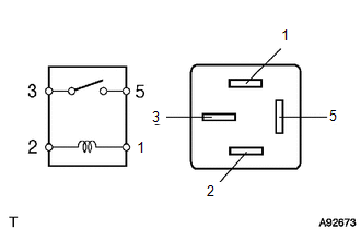
(b) Measure the resistance according to the value(s) in the table below.
Standard Resistance:
|
Tester Connection |
Condition |
Specified Condition |
|---|---|---|
|
3 - 5 |
Battery voltage is not applied between terminals 1 and 2 |
10 kΩ or higher |
|
Battery voltage is applied between terminals 1 and 2 |
Below 1 Ω |
| NG | |
REPLACE IGNITION RELAY NO. 1 |
|
|
3. |
CHECK HARNESS AND CONNECTOR (ECU - BATTERY AND BODY GROUND) |
|
(a) Disconnect the D31 ECU connector. |
|
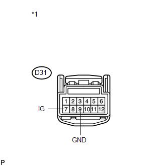
(b) Measure the voltage according to the value(s) in the table below.
Standard Voltage:
|
Tester Connection |
Switch Condition |
Specified Condition |
|---|---|---|
|
D31-7 (IG) - Body ground |
Ignition switch ON |
11 to 14 V |
|
Ignition switch off |
Below 1 V |
|
*1 |
Front view of wire harness connector (to Tire Pressure Warning ECU) |
(c) Measure the resistance according to the value(s) in the table below.
Standard Resistance:
|
Tester Connection |
Condition |
Specified Condition |
|---|---|---|
|
D31-9 (GND) - Body ground |
Always |
Below 1 Ω |
| OK | |
PROCEED TO NEXT SUSPECTED AREA SHOWN IN PROBLEM SYMPTOMS TABLE |
| NG | |
REPAIR OR REPLACE HARNESS OR CONNECTOR |
 Transmitter ID1 Operation Stop (C2111/11-C2114/14)
DESCRIPTION
The tire pressure warning valve and transmitter installed in each tire and wheel
assembly measures the tire pressures. The measured values are transmitted as radio
waves to the tire p ...
 Tire Pressure Warning Light Circuit
DESCRIPTION
If the tire pressure warning ECU detects a malfunction, the tire pressure warning
light blinks for 1 minute then stays on and tire pressure monitor is canceled at
the same time. At th ...
Other materials about Toyota Venza:
Cruise Main Indicator Light Circuit
DESCRIPTION
The ECM detects a cruise control main switch signal and sends it to
the combination meter assembly through CAN. Then the CRUISE main indicator
light comes on.
The CRUISE main indicator light circuit uses CAN for communication.
...
Open in Rear Floor Electrical Key Oscillator Circuit (B27A6)
DESCRIPTION
The certification ECU (smart key ECU assembly) generates a request signal and
sends it to the indoor electrical key oscillator (for center floor). To detect the
key inside the cabin, the indoor electrical key oscillator (for center floor) crea ...
Power Source Mode does not Change to ON (IG)
DESCRIPTION
When the engine switch is pushed with the electrical key in the cabin, the power
management control ECU receives signals to change the power source mode.
HINT:
To allow use of the Techstream to inspect the push-button start function when
the ...

0.1604