Toyota Venza: TC and CG Terminal Circuit
DESCRIPTION
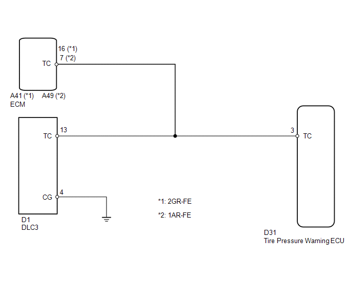
DTC output mode is set by connecting terminals 13 (TC) and 4 (CG) of the DLC3. The DTCs are indicated by the blinking pattern of the tire pressure warning light.
WIRING DIAGRAM
HINT:
When various warning lights blink continuously, a ground short in terminal TC of the DLC3 or an internal ground short in an ECU connected to this circuit may have occurred.
CAUTION / NOTICE / HINT
NOTICE:
- When replacing the tire pressure warning ECU, read the transmitter IDs stored in the old ECU using the Techstream and write them down before removal.
- It is necessary to perform registration (See page
.gif) ) of the transmitter IDs into the tire
) of the transmitter IDs into the tire
pressure warning ECU after the ECU has been replaced.
PROCEDURE
|
1. |
CHECK HARNESS AND CONNECTOR (DLC3 - TIRE PRESSURE WARNING ECU) |
|
(a) Disconnect the D31 ECU connector. |
|
(b) Measure the resistance according to the value(s) in the table below.
Standard Resistance:
|
Tester Connection |
Condition |
Specified Condition |
|---|---|---|
|
D31-3 (TC) - D1-13 (TC) |
Always |
Below 1 Ω |
|
D1-4 (CG) - Body ground |
|
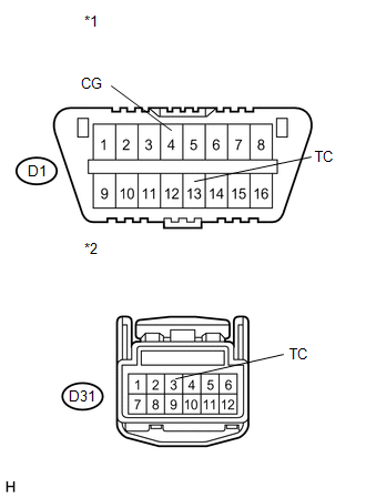
*1 |
Front view of wire harness connector (to DLC3) |
|
*2 |
Front view of wire harness connector (to Tire Pressure Warning ECU) |
| OK | .gif) |
PROCEED TO NEXT SUSPECTED AREA SHOWN IN PROBLEM SYMPTOMS TABLE |
| NG | |
REPAIR OR REPLACE HARNESS OR CONNECTOR |
 Tire Pressure Warning Light Circuit
DESCRIPTION
If the tire pressure warning ECU detects a malfunction, the tire pressure warning
light blinks for 1 minute then stays on and tire pressure monitor is canceled at
the same time. At th ...

Other materials about Toyota Venza:
Position Initialization Incomplete (B2343)
DESCRIPTION
This DTC is output when the sliding roof ECU (sliding roof drive gear sub-assembly)
has not been initialized.
DTC Code
DTC Detection Condition
Trouble Area
B2343
Sliding roof ECU (sli ...
Reassembly
REASSEMBLY
PROCEDURE
1. INSTALL BRAKE MASTER CYLINDER RESERVOIR ASSEMBLY
(a) Apply a light layer of lithium soap base glycol grease to the entire circumference
of 2 new brake master cylinder reservoir grommets.
(b) Install the 2 brake master cylinder res ...
Canceling the power back door system (vehicles with power back door)
Turn the main switch to disable the power back door system.
1. Inoperative
2. Operative
The back door cannot be operated even with the wireless remote control or power
back door switch.
A buzzer will sound twice if the power back door switch is pressed ...

0.1154